ASSEMBLY

STEP2: Attach ControlRods

WARNING

The control rods are adjusted at the factory and should not require additional adjustment during assembly. After as- sembling unit, controlrod ad- justment should be checked (and re-adjusted, if neces- sary) accordingto information in "Customer Responsibili- ties" Section. Severe person-

a] injury or property damage could result from

not following this instruction.

A.AttachWheel DriveControl Rod

AB

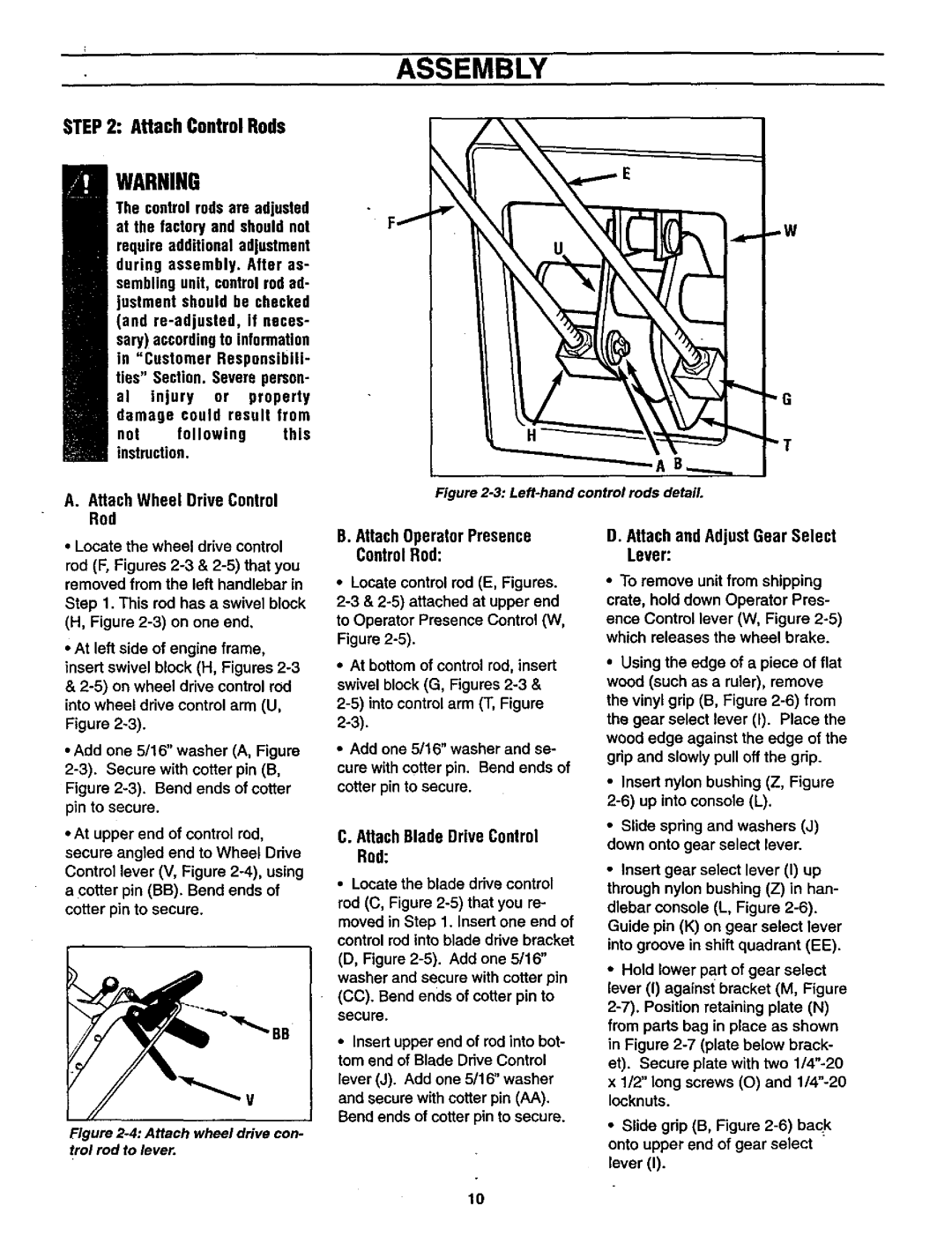
Figure 2-3: Left-hand control rods detail.

Locate the wheel drive control

rod (F, Figures 2-3 & 2-5) that you removed from the left handlebar in

Step 1. This rod has a swivel block (H, Figure 2-3) on one end.

At left side of engine frame, insert swivel block (H, Figures 2-3 & 2-5) on wheel drive control rod

into wheel drive control arm (U,

Figure 2-3).

• Add one 5/16" washer (A, Figure 2-3). Secure with cotter pin (B, Figure 2-3). Bend ends of cotter pin to secure.

At upper end of control rod, secure angled end to Wheel Drive Control lever (V, Figure 2-4), using a cotter pin (BB). Bend ends of cotter pin to secure.

B

V

Figure 2-4: Attach wheel drive con- trol rod to lever.

B.AttachOperatorPresence ControlRod:

Locate control rod (E, Figures. 2-3 & 2-5)attached at upper end to Operator Presence Control (W, Figure 2-5).

At bottom of control rod, insert swivel block (G, Figures 2-3& 2-5) into control arm (T, Figure

2-3).

Add one 5/16" washer and se-

cure with cotter pin. Bend ends of

cotter pin to secure.

C. AttachBlade DriveControl Rod:

Locate the blade drive control rod (C, Figure 2-5)that you re- moved in Step 1. Insert one end of control red into blade drive bracket (D, Figure 2-5). Add one 5/16" washer and secure with cotter pin (CC). Bend ends of cotter pin to secure.

Insert upper end of rod into bot- tom end of Blade Drive Control

lever (J). Add one 5/16" washer and secure with cotter pin (AA).

Bend ends of cotter pin to secure.

D.Attachand AdjustGear Select Lever:

To remove unit from shipping crate, hold down Operator Pres-

ence Control lever (W, Figure 2-5) which releases the wheel brake.

Using the edge of a piece of flat wood (such as a ruler), remove the vinyl grip (B, Figure 2-6) from the gear select lever (I). Place the wood edge against the edge of the grip and slowly pull off the grip.

Insert nylon bushing (Z, Figure

2-6)up into console (L).

Slide spring and washers (J) down onto gear select lever.

Insert gear select lever (I) up

through nylon bushing (Z) in han- dlebar console (L, Figure 2-6). Guide pin (K) on gear select lever into groove in shift quadrant (EE).

Hold lower part of gear select lever (I) against bracket (M, Figure 2-7). Position retaining plate (N) from parts bag in place as shown in Figure 2-7 (plate below brack- et). Secure plate with two 1/4"-20 x 1/2" long screws (O) and 1/4"-20 Iocknuts.

Slide grip (B, Figure 2-6) back onto upper end of gear select lever (I).

10

Page 10
Image 10
Craftsman 987.889 owner manual Attach ControlRods, AttachWheel DriveControl Rod, AttachOperatorPresence ControlRod

987.889 specifications

The Craftsman 987.889 is a versatile and powerful tool that embodies the hallmark of durability and performance. Known for its exceptional build quality, this tool is designed to meet the needs of both amateur and professional users alike.

One of the main features of the Craftsman 987.889 is its robust motor. With a high-performance engine, it delivers consistent power and efficiency, making it capable of handling a wide range of tasks. Whether you are tackling heavy-duty applications or precision jobs, the motor ensures optimal performance.

The Craftsman 987.889 incorporates advanced technology that sets it apart in the market. Its innovative design includes ergonomic handles that provide a comfortable grip, reducing user fatigue during extended use. The tool also features an adjustable speed setting, allowing users to customize their experience based on the specific project at hand. This flexibility is invaluable for tasks that require precision or for those that demand high power.

Durability is another key characteristic of the Craftsman 987.889. Constructed from high-quality materials, this tool is built to withstand the rigors of tough job sites. The weather-resistant casing ensures that it can be used in various conditions, making it an ideal choice for outdoor projects or in diverse environments.

Safety is paramount with the Craftsman 987.889, which includes built-in safety features. The tool is equipped with an automatic shut-off function that activates if it overheats or experiences excessive strain. This not only protects the user but also extends the life of the tool.

In addition to its standout features, the Craftsman 987.889 also offers compatibility with a wide range of accessories and attachments, enhancing its versatility. Users can easily switch out components, making it suitable for different applications such as woodworking, metalworking, or DIY projects.

Overall, the Craftsman 987.889 is a powerful, reliable, and user-friendly tool that meets the demands of modern craftsmanship. Its combination of advanced technology, ergonomic design, and safety features make it an excellent addition to any toolbox, ensuring that users can tackle projects with confidence and efficiency. Whether for professional use or personal projects, the Craftsman 987.889 is a tool that delivers performance and reliability with every use.