All installations and services must be performed by qualified service personnel.
I.BLOWER CONTROLLER INFORMATION
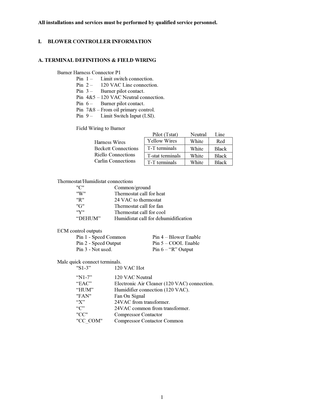
A. TERMINAL DEFINITIONS & FIELD WIRING |
|
| |||
Burner Harness Connector P1 |
|
|
| ||
Pin | 1 – | Limit switch connection. |
|
| |
Pin 2 – | 120 VAC Line connection. |
|
| ||
Pin | 3 – | Burner pilot contact. |
|
|
|
Pin 4&5 – 120 VAC Neutral connection. |
|
| |||
Pin | 6 – | Burner pilot contact. |
|
|
|
Pin | 7&8 – From oil primary control. |
|
| ||
Pin | 9 – | Limit Switch Input (LSI). |
|
| |
Field Wiring to Burner | Pilot (Tstat) | Neutral | Line | ||
|
|
| |||
|
| Harness Wires | Yellow Wires | White | Red |
|
| Beckett Connections | White | Black | |
|
| Riello Connections |
|
|
|
|
| White | Black | ||
|
| Carlin Connections | White | Black | |
Thermostat/Humidistat connections |
| |
"C" | Common/ground |
|
"W" | Thermostat call for heat | |
"R" | 24 VAC to thermostat | |
"G" | Thermostat call for fan | |
"Y" | Thermostat call for cool | |
“DEHUM” | Humidistat call for dehumidification | |
ECM control outputs |
|
|
Pin 1 - Speed Common | Pin 4 – Blower Enable | |
Pin 2 - Speed Output | Pin 5 – COOL Enable | |
Pin 3 - Not used. |
| Pin 6 – “R” Output |
Male quick connect terminals. |
| |
120 VAC Hot |
| |
120 VAC Neutral |
| |
“EAC” | Electronic Air Cleaner (120 VAC) connection. | |
“HUM” | Humidifier connection (120 VAC). | |
"FAN" | Fan On Signal |
|
“X” | 24VAC from transformer. | |
“C” | 24VAC common from transformer. | |
"CC" | Compressor Contactor | |
"CC_COM" | Compressor Contactor Common | |
1