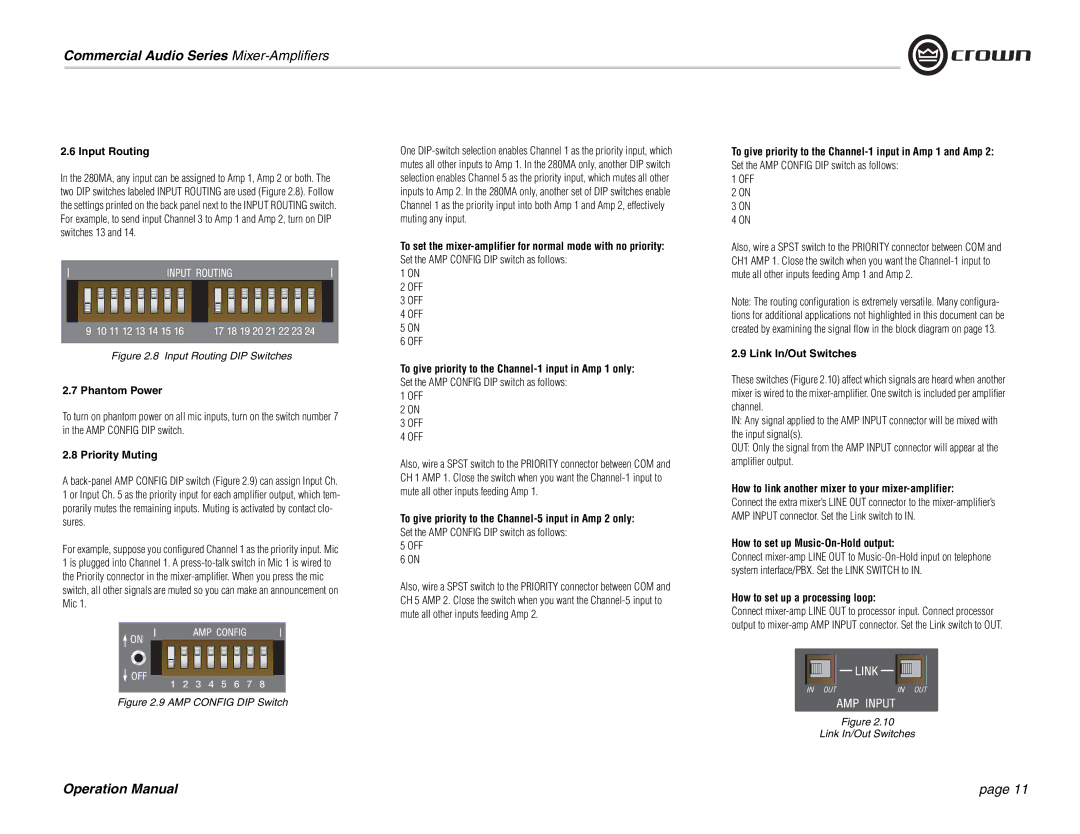
1160MA, 180MA 280MA specifications
Crown Audio, a leader in professional amplifier technology, has introduced a series of high-performance amplifiers that cater to a variety of applications. The 1160MA, 180MA, and 280MA models are designed to deliver exceptional sound quality, reliability, and efficiency, making them ideal for both commercial and residential audio installations.The 1160MA is a versatile amplifier equipped with a powerful, high-efficiency Class D design that ensures maximum power output with minimal heat generation. Capable of delivering up to 1,160 watts per channel, this model is perfect for driving moderate-sized sound systems, whether in a church, auditorium, or live event. Its 70V and 100V compatibility allows for easy integration into existing audio setups, making it suitable for various applications.
The 180MA boasts a lower power output while retaining the same high-quality audio performance that Crown is renowned for. With 180 watts per channel, it is perfect for smaller installations where space and power consumption are considerations. This amplifier also features built-in processing capabilities, allowing users to fine-tune audio output to suit specific acoustic environments. Its compact design and robust construction make it a reliable choice for both permanent installations and portable setups.
The 280MA stands out with its increased power capacity, offering up to 280 watts per channel. It is designed to handle larger loads, making it ideal for venues that require robust sound reinforcement. Like its counterparts, the 280MA features advanced thermal management technology, ensuring reliable operation even during extended use. The inclusion of both analog and digital inputs provides versatility in connectivity, accommodating traditional audio systems alongside modern digital setups.
All three models share some key features, including an intuitive front-panel LCD for easy monitoring of performance metrics and settings. They also include comprehensive protection circuitry, safeguarding against over-voltage, over-current, and thermal overload, thereby ensuring long-term reliability.
In summary, the Crown Audio 1160MA, 180MA, and 280MA amplifiers excel in delivering high-fidelity audio across a range of applications. With their efficient Class D technology, advanced processing options, and robust construction, these amplifiers represent a union of power and flexibility, catering to audio professionals seeking performance and reliability in their sound systems.

