Manuals
/
Crown Audio
/
Home Audio
/
Stereo Amplifier
Crown Audio
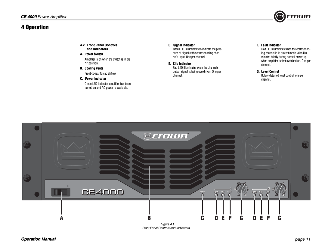
ce 4000 Operation, CE 4000 Power Amplifier, page, A.Power Switch, C.Power Indicator
Models:
ce 4000
1
11
24
24
Download
24 pages
60.45 Kb
8
9
10
11
12
13
14
15
Troubleshooting
Install
Fault
C.Power Indicator
Choose Input Wire
Warranty
Nature Of Problem
Setup
Output Connectors
How to
Page 11
Image 11
Page 10
Page 12
Page 11
Image 11
Page 10
Page 12
Contents
Some models may be exported under the name Amcron
CE Series
page
Important Safety Instructions
CE 4000 Power Amplifier
CE 4000 Power Amplifier
DECLARATION OF CONFORMITY
page
page
Table of Contents
CE 4000 Power Amplifier
1.1 Features
2 How to Use This Manual
1 Welcome
CE 4000 Power Amplifier
Figure 3.2 Airflow Figure 3.1 Dimensions
3 Setup
CE 4000 Power Amplifier
3.2 Install Your Amplifier
and Connectors
3 Setup
CE 4000 Power Amplifier
3.4 Choose Input Wire
Figure 3.5 Speakon Output Connector Wiring
3 Setup
CE 4000 Power Amplifier
3.5Choose Output Wire and Connectors
page
3 Setup
CE 4000 Power Amplifier
3.6.2 How to Parallel the Inputs
page
4 Operation
3 Setup
CE 4000 Power Amplifier
D.Signal Indicator
CE 4000 Power Amplifier
A.Power Switch
C.Power Indicator
4 Operation
CE 4000 Power Amplifier
4.3Back Panel Controls and Connectors
Figure 4.2 Back Panel Controls and Connectors
5.2.2Switching Power Supply with PFC
5 Advanced Features and Options
CE 4000 Power Amplifier
5.1.2 Fault
5.3.2 Neutrik Speakon Wiring
CE 4000 Power Amplifier
5.3 Other Features
Switch
CONDITION Distorted sound
6 Troubleshooting
CONDITION No power to the amplifier
CONDITION Normal operation
CE 4000 Power Amplifier
Minimum Guaranteed Power watts
7 Specifications
Performance
page
Construction
CE 4000 Power Amplifier
7 Specifications
574-294-8301 Technical Support
8 Service
Crown Factory Service
574-294-8124 Factory Service
SUMMARY OF WARRANTY
9 Warranty
YEAR
CE 4000 Power Amplifier
HOW TO OBTAIN WARRANTY SERVICE
3 YEAR
9 Warranty
CE 4000 Power Amplifier
If warranty has expired, payment will be
Crown Factory Service Information
CE 4000 Power Amplifier
NATURE OF PROBLEM
page
CE 4000 Power Amplifier
THIS PAGE INTENTIONALLY LEFT BLANK
page
CE 4000 Power Amplifier
Top
Page
Image
Contents