Voltage Gain (at maximum level setting):
8/4 ohm operation, 1.4V sensitivity CTs 600 35:1 (31 dB)
CTs 1200 50:1 (34 dB)
CTs 2000 63.9:1 (36 dB)
CTs 3000 71.4:1 (37 dB).
26 dB: 20:1 (26 dB).
70V operation, 1.4V sensitivity or 100V opera- tion, 2.0V sensitivity: 50:1 (34 dB).
AC Line Voltage and Frequency Configurations Available (±10%): 120VAC/60Hz, 230VAC/50 Hz.
Power Draw at Idle (120VAC mains):
CTs 600/1200: 24W (standby mode)
CTs 2000/3000: 35W (standby mode).
Cooling: Continuously variable speed forced air, front-to-back airflow.
Dimensions: 19 in. (48.3 cm) W x 3.5 in. (8.9 cm) H x 14.25 in. (36.2 cm) D.
Weight: Net, Shipping
CTs 600: 22.8 lb (10.3 kg), 27.7 lb (12.6 kg)
CTs 1200: 23.4 lb (10.6 kg), 28.3 lb (12.8 kg)
CTs 2000: 27.0 lb (12.2 kg), 32.0 lb (14.5 kg)
CTs 3000: 27.7 lb (12.6 kg), 32.7 lb (14.8 kg).
Front Panel Controls and Indicators
Bridge Mode Indicator: Yellow LED illuminates when the rear-panel Mode Switch is set to the “Bridge” position.
Ready Indicator: Green LED, one per channel, illuminates when the channel is initialized and ready to produce audio output. Indicator is off when PIP puts the amplifier in standby mode via the control system.
Signal Indicators: Three green LEDs per channel indicate the amplifier’s input and output signal levels.
Signal: input signal is above –40 dBu.
–20 dB: amplifier output is 20 dB below clipping.
–10 dB: amplifier output is 10 dB below clipping.
Clip Indicator: Red LED, one per channel, illumi- nates when the channel’s output signal reaches the
onset of audible clipping. The Clip Indicator also will illuminate during Thermal Level Control (TLC) limiting or when the input compressor/limiter is protecting the amplifier from input overload.
Thermal Indicator: Red LED, one per channel, illuminates when the channel has shut down, or is very near shutting down, due to thermal stress or overload.
Fault Indicator: Red LED, one per channel, flashes when the amplifier output channel has stopped operating.
Data Indicator: Yellow LED indicates control data activity (if the amplifier is equipped with an IQ- PIP2 module, and connected to a control system).
Power Indicator: Blue LED indicates amplifier has been turned on and AC power is available. The LED will flash when the AC line voltage is 15% above or 25% below the nominal rated value.
Cooling Vents: Front-to-rear forced airflow.
Power Switch: Push-on / push-off switch.
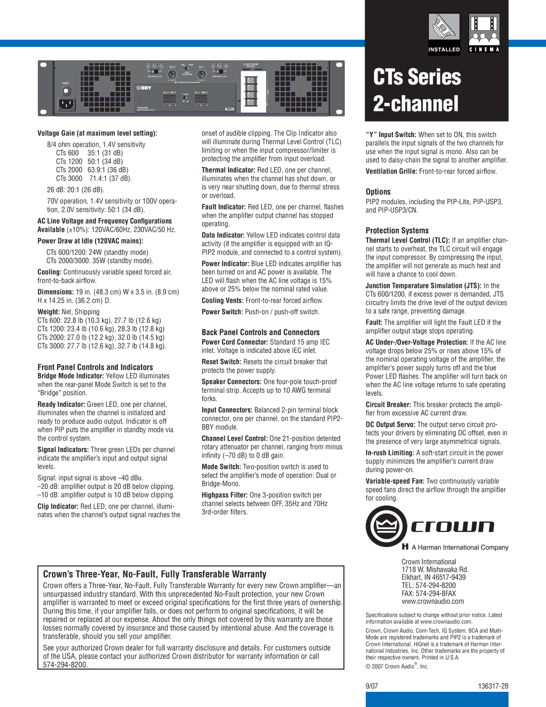
Back Panel Controls and Connectors
Power Cord Connector: Standard 15 amp IEC inlet. Voltage is indicated above IEC inlet.
Reset Switch: Resets the circuit breaker that protects the power supply.
Speaker Connectors: One four-poletouch-proof terminal strip. Accepts up to 10 AWG terminal forks.
Input Connectors: Balanced 2-pin terminal block connector, one per channel, on the standard PIP2- BBY module.
Channel Level Control: One 21-position detented rotary attenuator per channel, ranging from minus infinity (–70 dB) to 0 dB gain.
Mode Switch: Two-position switch is used to
select the amplifier’s mode of operation: Dual or Bridge-Mono.
Highpass Filter: One 3-position switch per channel selects between OFF, 35Hz and 70Hz 3rd-order filters.
CTs Series 2-channel
“Y” Input Switch: When set to ON, this switch parallels the input signals of the two channels for use when the input signal is mono. Also can be used to daisy-chain the signal to another amplifier.
Ventilation Grille: Front-to-rear forced airflow.
Options
PIP2 modules, including the PIP-Lite, PIP-USP3, and PIP-USP3/CN.
Protection Systems
Thermal Level Control (TLC): If an amplifier chan- nel starts to overheat, the TLC circuit will engage the input compressor. By compressing the input, the amplifier will not generate as much heat and will have a chance to cool down.
Junction Temperature Simulation (JTS): In the CTs 600/1200, if excess power is demanded, JTS circuitry limits the drive level of the output devices to a safe range, preventing damage.
Fault: The amplifier will light the Fault LED if the amplifier output stage stops operating.
AC Under-/Over-Voltage Protection: If the AC line voltage drops below 25% or rises above 15% of the nominal operating voltage of the amplifier, the amplifier’s power supply turns off and the blue Power LED flashes. The amplifier will turn back on when the AC line voltage returns to safe operating levels.
Circuit Breaker: This breaker protects the ampli- fier from excessive AC current draw.
DC Output Servo: The output servo circuit pro- tects your drivers by eliminating DC offset, even in the presence of very large asymmetrical signals.
In-rush Limiting: A soft-start circuit in the power supply minimizes the amplifier’s current draw during power-on.
Variable-speed Fan: Two continuously variable speed fans direct the airflow through the amplifier for cooling.
Crown’s Three-Year, No-Fault, Fully Transferable Warranty
Crown offers a Three-Year, No-Fault, Fully Transferable Warranty for every new Crown amplifier—an unsurpassed industry standard. With this unprecedented No-Fault protection, your new Crown amplifier is warranted to meet or exceed original specifications for the first three years of ownership. During this time, if your amplifier fails, or does not perform to original specifications, it will be repaired or replaced at our expense. About the only things not covered by this warranty are those losses normally covered by insurance and those caused by intentional abuse. And the coverage is transferable, should you sell your amplifier.
See your authorized Crown dealer for full warranty disclosure and details. For customers outside of the USA, please contact your authorized Crown distributor for warranty information or call 574-294-8200.
Crown International 1718 W. Mishawaka Rd. Elkhart, IN 46517-9439 TEL: 574-294-8200 FAX: 574-294-8FAX www.crownaudio.com
Specifications subject to change without prior notice. Latest information available at www.crownaudio.com.
Crown, Crown Audio, Com-Tech, IQ System, BCA and Multi- Mode are registered trademarks and PIP2 is a trademark of Crown International. HiQnet is a trademark of Harman Inter- national Industries, Inc. Other trademarks are the property of their respective owners. Printed in U.S.A.
© 2007 Crown Audio®, Inc.