STUDIO AMPLIFIER specifications
Crown Audio, a leader in professional audio solutions, has long been renowned for producing high-quality amplifiers, and their Studio Amplifier series exemplifies this reputation. The Crown Studio Amplifier is meticulously engineered for audiophiles and professionals seeking excellence in sound reproduction, characterized by its superior performance, reliability, and advanced features.At the heart of the Crown Studio Amplifier lies its robust power output, designed to deliver pristine audio quality at high volumes without distortion. With various models available, users can choose from a range of power ratings, ensuring they have the right amount of amplification for their specific needs. This versatility makes the amplifier suitable for various applications, including recording studios, live sound environments, and high-fidelity home listening.
One of the standout features of the Crown Studio Amplifier is its advanced signal processing technology. The unit includes built-in DSP (Digital Signal Processing), which allows users to tailor the audio output with precision. This feature enables various EQ settings and dynamic range adjustments that enhance sound clarity and compensate for room acoustics, making it an essential tool for audio engineers and sound designers.
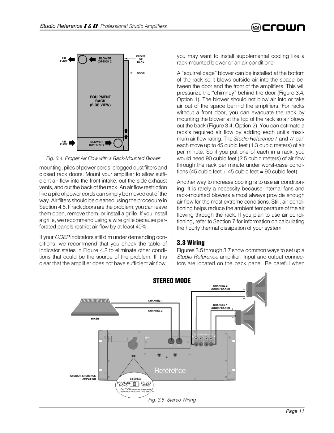
Further enhancing its capabilities, the Crown Studio Amplifier is designed with a sophisticated thermal management system that ensures optimal performance even during prolonged usage. Users can rely on its ability to maintain consistent output without overheating, which is crucial during demanding sessions, whether in the studio or at a live event.
Moreover, the Crown Studio Amplifier boasts a user-friendly interface, featuring intuitive controls that simplify operation. The LCD display provides vital information at a glance, allowing users to monitor levels, settings, and system status easily. This focus on usability enhances the overall experience, allowing professionals to concentrate on their craft rather than getting bogged down in technical complexities.
In addition to outstanding performance, the Crown Studio Amplifier is built for durability and longevity. The rugged chassis and high-quality components are designed to withstand the rigors of the road, making it a reliable choice for touring musicians and sound technicians alike.
With its impressive combination of power, advanced technology, and user-friendly features, the Crown Studio Amplifier continues to set a high standard in the audio industry, making it an ideal choice for anyone serious about sound quality. Whether for studio work, live performances, or home audio setups, the Crown Studio Amplifier delivers exceptional fidelity and reliability, upholding Crown's legacy of excellence in professional audio.

