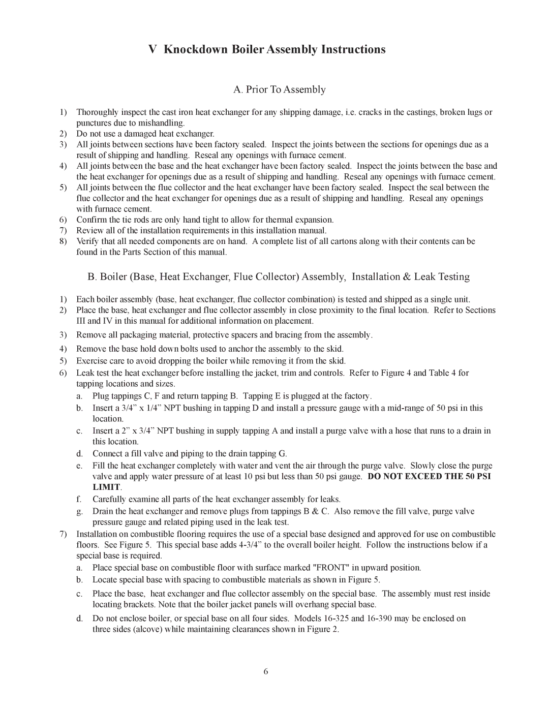
16-325 500506 specifications
The Crown Boiler 16-325 500506 is a highly reliable heating solution designed for residential and light commercial applications. Known for its robust construction and advanced technologies, this boiler is engineered to deliver efficient heating while ensuring longevity and minimal maintenance.One of the standout features of the Crown Boiler 16-325 is its durable steel construction, which is essential for handling the high temperatures and pressures involved in heating systems. The boiler is typically equipped with a cast iron heat exchanger, known for its excellent heat retention and distribution capabilities. This ensures that the system heats up quickly and maintains consistent temperatures throughout the space.
The boiler's capacity to produce 325,000 BTUs makes it suitable for larger homes or commercial buildings with significant heating demands. Its high input capacity allows for effective operation in areas where traditional systems may struggle to keep up with heating requirements. The Crown Boiler 16-325 employs a forced hot water system, which circulates water through pipes and radiators, providing uniform heat and comfort in indoor spaces.
A significant technological advancement in this model is its integrated control system. The advanced control module automates burner operation, ensuring optimal performance while minimizing energy consumption. This technology not only enhances efficiency but also helps in reducing operational costs, making it a cost-effective choice for users.
Moreover, the Crown Boiler 16-325 is designed with ease of installation and maintenance in mind. It features convenient access panels that simplify the maintenance process, allowing technicians to perform service checks and repairs without extensive downtime. This attribute is particularly beneficial for property managers or homeowners looking for a hassle-free heating solution.
In terms of safety features, the boiler is equipped with a pressure relief valve and a low-water cutoff switch, ensuring safe operation while protecting against potential hazards associated with overheating or lack of water.
Overall, the Crown Boiler 16-325 500506 is a powerful and efficient heating solution that excels in durability and performance. With its advanced technologies, substantial heating capacity, and user-friendly design, it represents an excellent choice for those seeking a reliable heating system that combines efficiency with long-term operational savings.
