OPERATION
Know Your Mower
Read this operator’s manual and safety rules before operating your Mower. Compare the illustrations below with your equipment to familiarize yourself with the location of various controls, safety signs and adjustments. Save this manual for future reference.
The operation of any lawn mower can result in foreign objects being thrown into the eyes, which can damage your eye severely. Always wear safety glasses, while operating the mower or while performing any adjustments or repairs on it. Check local regulations, hard hats and hearing protection may be required! Use only approved accessories and attachments.
| 6 |
|
2 | 1 | 4 |
|
7
8
5 3
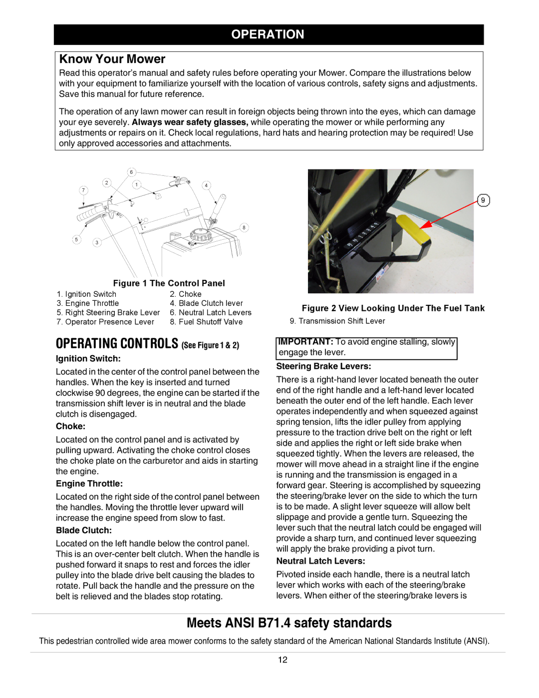
Figure 1 The Control Panel
1. | Ignition Switch | 2. | Choke |
3. | Engine Throttle | 4. | Blade Clutch lever |
5. | Right Steering Brake Lever | 6. | Neutral Latch Levers |
7. | Operator Presence Lever | 8. | Fuel Shutoff Valve |
OPERATING CONTROLS (See Figure 1 & 2)
Ignition Switch:
Located in the center of the control panel between the handles. When the key is inserted and turned clockwise 90 degrees, the engine can be started if the transmission shift lever is in neutral and the blade clutch is disengaged.
Choke:
Located on the control panel and is activated by pulling upward. Activating the choke control closes the choke plate on the carburetor and aids in starting the engine.
Engine Throttle:
Located on the right side of the control panel between the handles. Moving the throttle lever upward will increase the engine speed from slow to fast.
Blade Clutch:
Located on the left handle below the control panel. This is an
Figure 2 View Looking Under The Fuel Tank
9. Transmission Shift Lever
IMPORTANT: To avoid engine stalling, slowly engage the lever.
Steering Brake Levers:
There is a
Neutral Latch Levers:
Pivoted inside each handle, there is a neutral latch lever which works with each of the steering/brake levers. When either of the steering/brake levers is
Meets ANSI B71.4 safety standards
This pedestrian controlled wide area mower conforms to the safety standard of the American National Standards Institute (ANSI).
12