highest (also transport position) or lowest (also for mower deck removal and installation).
The following features are incorporated into the hydraulic actuated valve implement lift design: Lever implement lift allows for some operators with physical limitations to use the implement lift mechanisms and the machine; reduces potential for operator fatigue; accommodates a variety of operator sizes, shapes, and strengths.
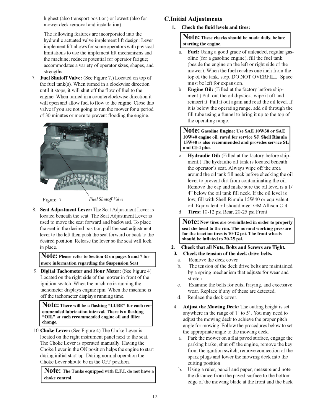
7.Fuel Shutoff Valve: (See Figure 7.) Located on top of the fuel tank(s). When turned in a clockwise direction until it stops, it will shut off the flow of fuel to the engine. When turned in a counterclockwise direction it will open and allow fuel to flow to the engine. Close this valve if you are not going to run the mower for a period of 30 minutes or more to prevent flooding the engine.
Figure. 7 | Fuel Shutoff Valve |
8.Seat Adjustment Lever: The Seat Adjustment Lever is located beneath the seat. The Seat Adjustment Lever is used to move the seat forward and backward. To place the seat in the desired position pull the seat adjustment lever to the left then push the seat forward or back to the desired position. Release the lever so the seat will lock in place.
Note: Please refer to Section G on pages 6 and 7 for more information regarding the Suspension Seat
9.Digital Tachometer and Hour Meter: (See Figure 4) Located on the right side of the mower in front of the ignition switch. When the machine is running the tachometer displays engine rpm. When the machine is off the tachometer displays running time.
Note: There will be a flashing “LUBE” for each rec- ommended lubrication interval. There is a flashing “OIL” at each recommended engine oil and filter change.
10.Choke Lever: (See Figure 4) The Choke Lever is located on the right instrument panel next to the seat. The Choke Lever is operated manually. Having the Choke Lever in the ON position helps the engine to start during initial
Note: The Tanks equipped with E.F.I. do not have a choke control.
C.Initial Adjustments
1.Check the fluid levels and tires:
Note: These checks should be made daily, before starting the engine.
a.Fuel: Using a good grade of unleaded, regular gas- oline (for a gasoline engine), fill the fuel tank (beside the engine on the left or right side of the mower). When the fuel reaches one inch from the top of the tank, stop. DO NOT OVERFILL. Space must be left for expansion.
b.Engine Oil: (Filled at the factory before ship- ment.) Pull out the oil dipstick, wipe it off and reinsert it. Pull it out again and read the oil level. If it is below the operating range, add oil through the fill tube using a funnel to bring it up to the top of the operating range.
Note: Gasoline Engine: Use SAE 10W30 or SAE 10W40 engine oil, rated for service SJ. Shell Rimula 15W40 is also recommended and provides service SL and
c.Hydraulic Oil: (Filled at the factory before ship- ment.) The hydraulic oil tank is located beneath the operator’s seat. Always wipe off the area around the oil tank fill neck before checking the oil level to prevent dirt from contaminating the oil. Remove the cap and make sure the oil level is a 1/ 4” below the oil tank fill neck. If the oil level is low, fill with Shell Rimula 15W40 or equivalent oil. Equivalent oil should meet GM Allison
d.Tires:
Note: New tires are overinflated in order to properly seat the bead to the rim. The normal working pressure for the traction tires is
2.Check that all Nuts, Bolts and Screws are Tight.
3.Check the tension of the deck drive belts.
a.Remove the deck cover
b.The tension of the deck drive belts are maintained by a spring mechanism that adjusts for wear and stretch.
c.Examine the belts for cuts, fraying, and excessive wear. Replace if any of these are detected.
d.Replace the deck cover.
4.Adjust the Mowing Deck: The cutting height is set anywhere in the range of 1" to 5". You may need to adjust the mowing deck to achieve the proper pitch angle for mowing. Follow the procedures below to set the appropriate angle to the mowing deck.
a.Park the mower on a flat paved surface, engage the parking brake, shut off the engine, remove the key from the ignition switch, remove connection of the spark plugs and lower the mowing deck into the cutting position.
b.Using a ruler, pencil and paper, measure and note the distance from the paved surface to the bottom edge of the mowing blade at the front and the back
12