g.
h.Do not stop machine or park machine over com- bustible materials such as dry grass, leaves, debris, etc.
3.To Mow Grass and Produce a Striped Pattern
a.Pick a point on the opposite side of the area to be mowed (post, tree, shrub, etc.).
b.If on an hillside, start at the bottom so that the turns are uphill rather than downhill.
c.Align the mower so as to head directly toward the object on the far side.
d.Slowly increase the speed of the machine to match cutting conditions, terrain, and operator familiarity with the controls and keep the machine headed directly toward the alignment object. Do not go fast as to reduce cut quality or to be uncomfortable in controlling the speed and direction of the machine.
e.When approaching the other end of a strip, slow down or stop before turning. A
f.Remember, a zero turn requires that the forward or reverse travel of the machine be stopped prior to the initiation of the turn or severe turf defacement can occur.
g.To prevent rutting or grooving of the turf, change the direction that the strips are mowed by approxi- mately 45 degrees the next and each subsequent time that the area is mowed.
B.Controls
1.Engine Ignition and Start Switch: (See Figure 4.) Located on the instrument housing below the right side of the operator’s seat. When the key is inserted and turned clockwise, 45 degrees, the ignition circuit is closed. Turning the switch further against spring pressure starts the engine. The engine will only start if the blade clutch switch is in the “off” position, the parking brake is engaged and the speed control pedals are in their neutral position. The key should always be removed from the switch if the operator leaves the mower’s seat.
2.Engine Throttle Control: (See Figure 4.) Located on the right side of the mower next to the operator’s seat. Moving the throttle control from the rear to the front will increase the engine speed from slow to fast.
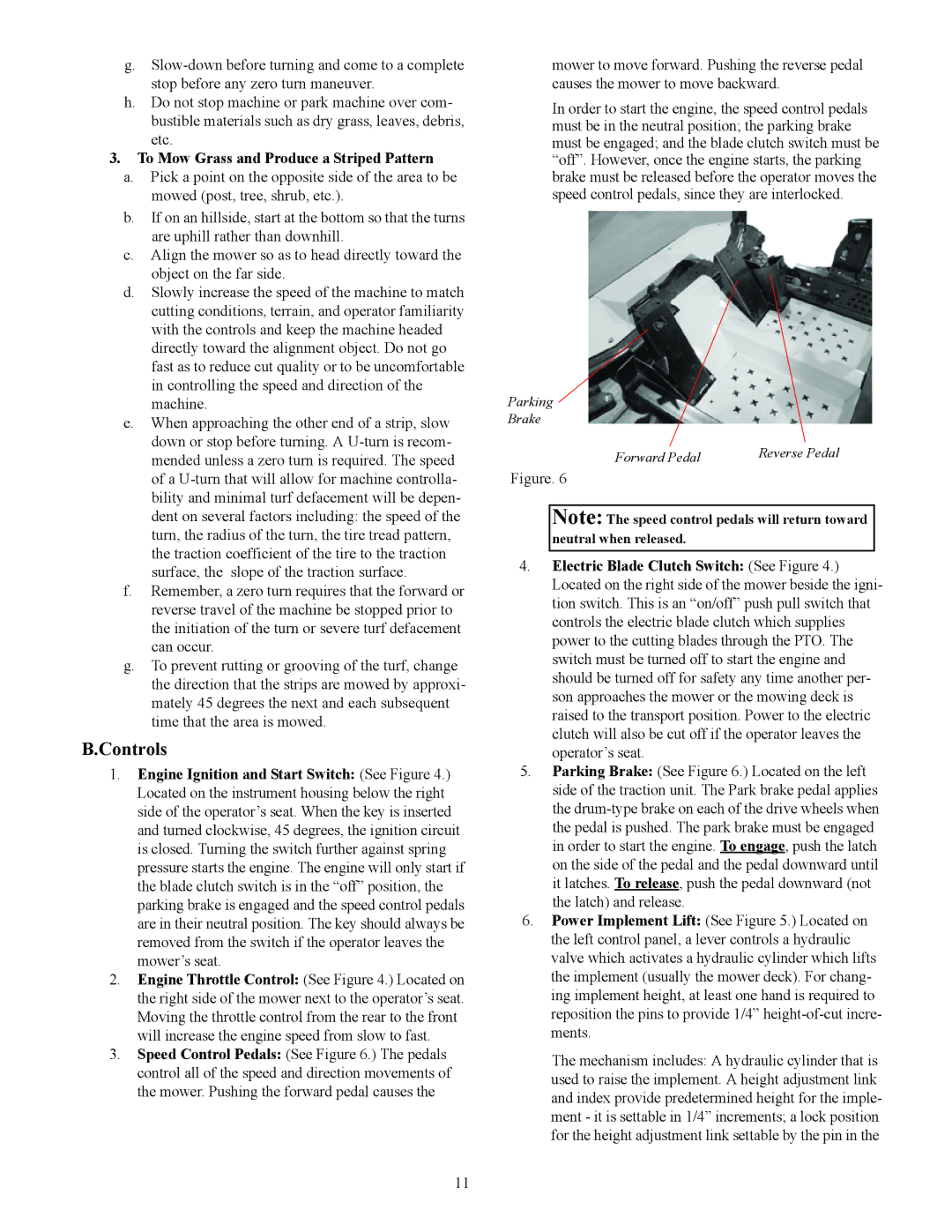
3.Speed Control Pedals: (See Figure 6.) The pedals control all of the speed and direction movements of the mower. Pushing the forward pedal causes the
mower to move forward. Pushing the reverse pedal causes the mower to move backward.
In order to start the engine, the speed control pedals must be in the neutral position; the parking brake must be engaged; and the blade clutch switch must be “off”. However, once the engine starts, the parking brake must be released before the operator moves the speed control pedals, since they are interlocked.
Parking
Brake
Forward Pedal | Reverse Pedal |
|
Figure. 6
Note: The speed control pedals will return toward neutral when released.
4.Electric Blade Clutch Switch: (See Figure 4.) Located on the right side of the mower beside the igni- tion switch. This is an “on/off” push pull switch that controls the electric blade clutch which supplies power to the cutting blades through the PTO. The switch must be turned off to start the engine and should be turned off for safety any time another per- son approaches the mower or the mowing deck is raised to the transport position. Power to the electric clutch will also be cut off if the operator leaves the operator’s seat.
5.Parking Brake: (See Figure 6.) Located on the left side of the traction unit. The Park brake pedal applies the
6.Power Implement Lift: (See Figure 5.) Located on the left control panel, a lever controls a hydraulic valve which activates a hydraulic cylinder which lifts the implement (usually the mower deck). For chang- ing implement height, at least one hand is required to reposition the pins to provide 1/4”
The mechanism includes: A hydraulic cylinder that is used to raise the implement. A height adjustment link and index provide predetermined height for the imple- ment - it is settable in 1/4” increments; a lock position for the height adjustment link settable by the pin in the
11