Manuals
/
CyberPower Systems
/
Computer Equipment
/
Power Supply
CyberPower Systems
CPS3000PIE Installation Guide, Power On Indicator, LCD Module Display, Step
Models:
CPS3000PIE
1
7
14
14
Download
14 pages
43.82 Kb
4
5
6
7
8
9
10
11
Troubleshooting
Specs
Install
Power On Indicator
Replacing The Battery
Power Switch
Solution
Page 7
Image 7
Page 6
Page 8
Page 7
Image 7
Page 6
Page 8
Contents
K01-0000010-00
CPS3000PIE USER MANUAL
FAULT WARNING DISPLAY AND ALARM……………………………………….………10
TABLE OF CONTENTS
SAFETY AND EMC INSTRUCTIONS………….……………………………………….………1
EPS STATUS INQUIRY AND FUNCTIONS SETUP…….……………………………………8
K01-0000010-00
SAFETY AND EMC INSTRUCTIONS SAVE THESE INSTRUCTIONS
DO NOT USE FOR MEDICAL OR LIFE SUPPORT EQUIPMENT
INSTALLING YOUR EPS
HARDWARE INSTALLATION GUIDE
UNPACKING
AUTOMATIC VOLTAGE REGULATOR
9. Power Switch
DESCRIPTION
7. Battery Input Wiring Fault LED
8. Bypass Switch
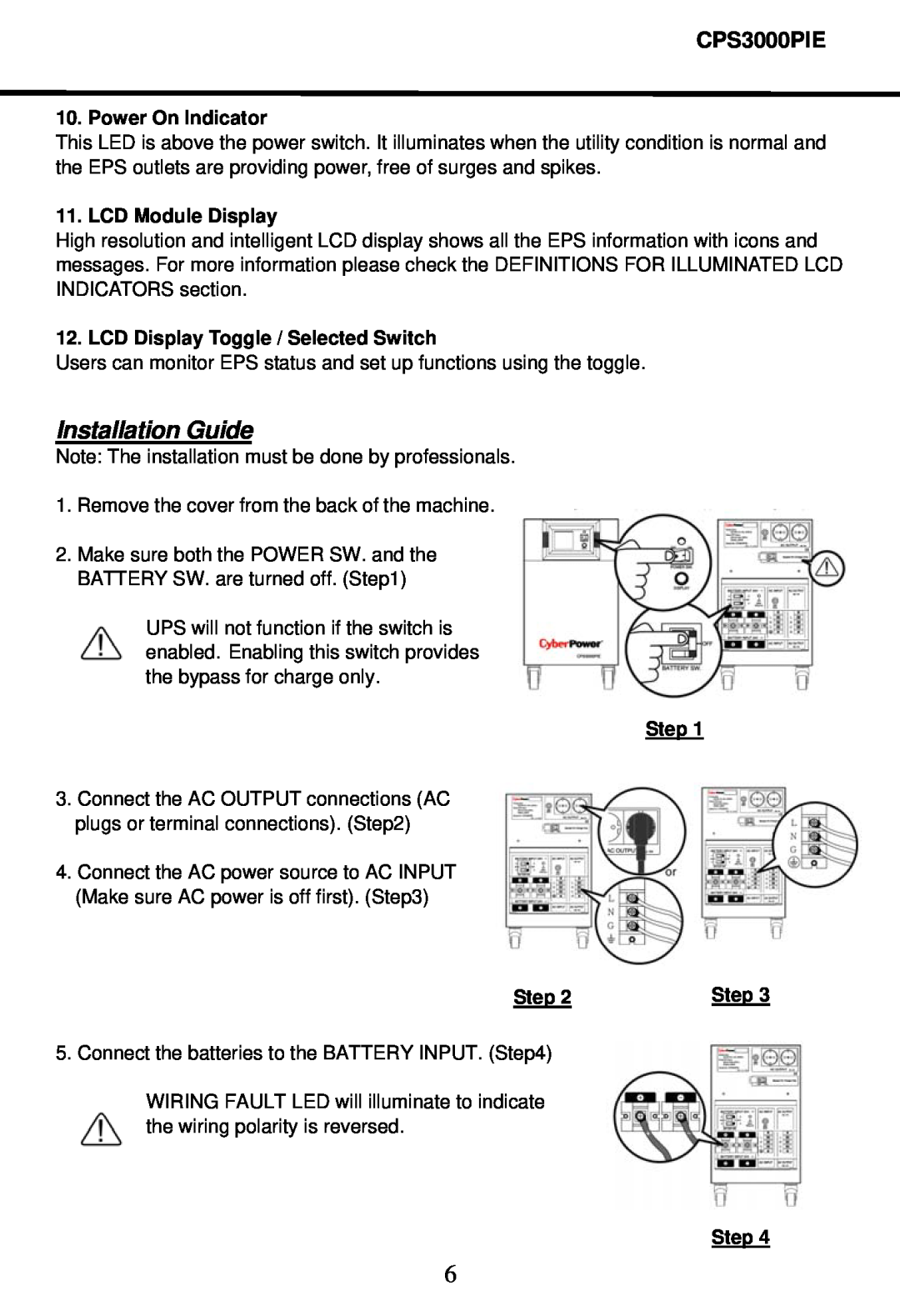
11. LCD Module Display
Installation Guide
10. Power On Indicator
12. LCD Display Toggle / Selected Switch
REPLACING THE BATTERY
ELECTRICAL SHOCK
DEFINITIONS FOR ILLUMINATED LCD
1. General Mode
EPS Status Inquiry and Functions Setup
Items
2. Set-up Mode
Unit
1. Wait for the backlight to turn off
FAULT WARNING DISPLAY AND ALARM
Solution
Condition
Possible Cause
TROUBLESHOOTING
Problem
Solution
CPS3000PIE
TECHNICAL SPECIFICATIONS
External Battery
Model
Top
Page
Image
Contents