Getting Started
2.4.4CapSense Proximity Sensing Demonstration
The CapSense proximity sensing demonstration shows how to use a proximity sensor to control LED color.
The proximity detector requires the use of a Proximity Antenna and can sense an object with approx- imately
The project is setup to recalculate this baseline approximately every 30 seconds. Also notice how the shape and position of the wire affects the demonstration operation and the proximity sensing dis- tance.
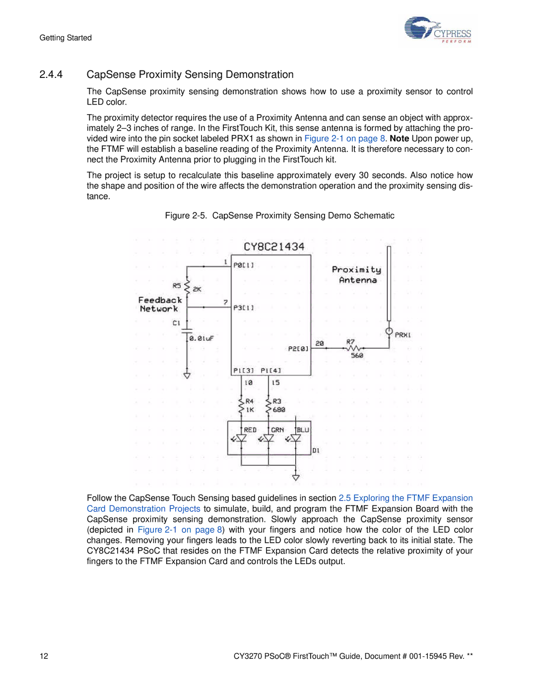
Figure 2-5. CapSense Proximity Sensing Demo Schematic
Follow the CapSense Touch Sensing based guidelines in section 2.5 Exploring the FTMF Expansion Card Demonstration Projects to simulate, build, and program the FTMF Expansion Board with the CapSense proximity sensing demonstration. Slowly approach the CapSense proximity sensor (depicted in Figure 2-1 on page 8) with your fingers and notice how the color of the LED color changes. Removing your fingers leads to the LED color slowly reverting back to its initial state. The CY8C21434 PSoC that resides on the FTMF Expansion Card detects the relative proximity of your fingers to the FTMF Expansion Card and controls the LEDs output.
12 | CY3270 PSoC® FirstTouch™ Guide, Document # |