CY62158E MoBL→
Switching Waveforms (continued)
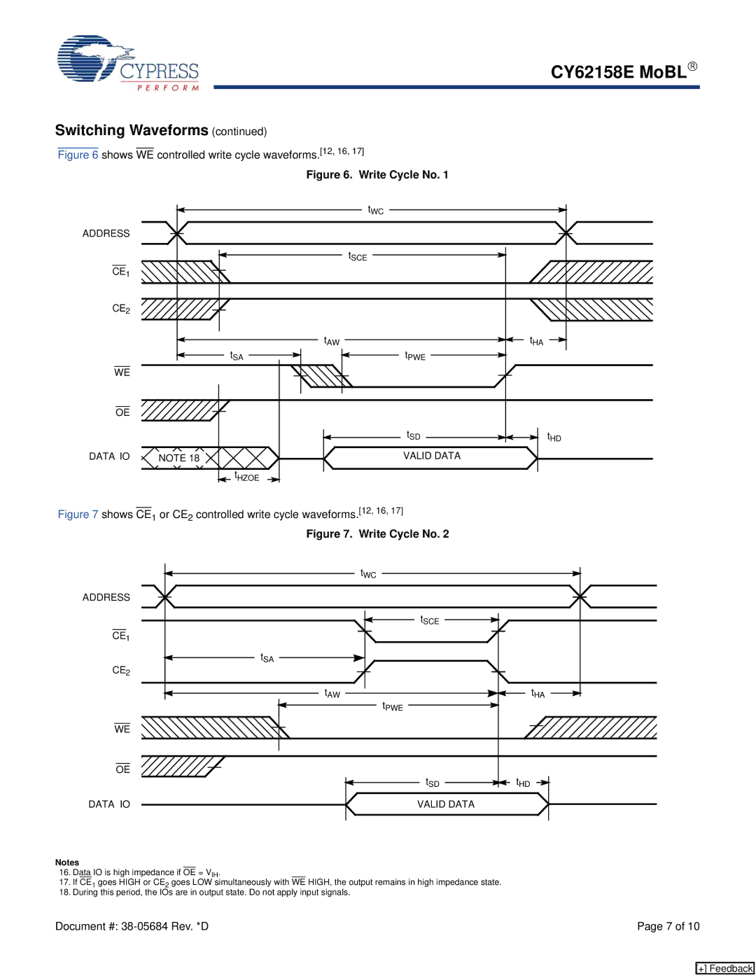
Figure 6 shows WE controlled write cycle waveforms.[12, 16, 17]
Figure 6. Write Cycle No. 1
|
| tWC |
|
ADDRESS |
|
|
|
|
| tSCE |
|
CE1 |
|
|
|
CE2 |
|
|
|
| tAW |
| tHA |
| tSA | tPWE |
|
WE |
|
|
|
OE |
|
|
|
|
| tSD | t |
|
|
| HD |
DATA IO | NOTE 18 | VALID DATA |
|
| tHZOE |
|
|
Figure 7 shows CE1 or CE2 controlled write cycle waveforms.[12, 16, 17]
Figure 7. Write Cycle No. 2
| tWC |
|
ADDRESS |
|
|
| tSCE |
|
CE1 |
|
|
tSA |
|
|
CE2 |
|
|
tAW | tPWE | tHA |
|
| |
WE |
|
|
OE | tSD | tHD |
| ||
DATA IO | VALID DATA |
|
Notes
16.Data IO is high impedance if OE = VIH.
17.If CE1 goes HIGH or CE2 goes LOW simultaneously with WE HIGH, the output remains in high impedance state.
18.During this period, the IOs are in output state. Do not apply input signals.
Document #: | Page 7 of 10 |
[+] Feedback
