CY7B991

CY7B992

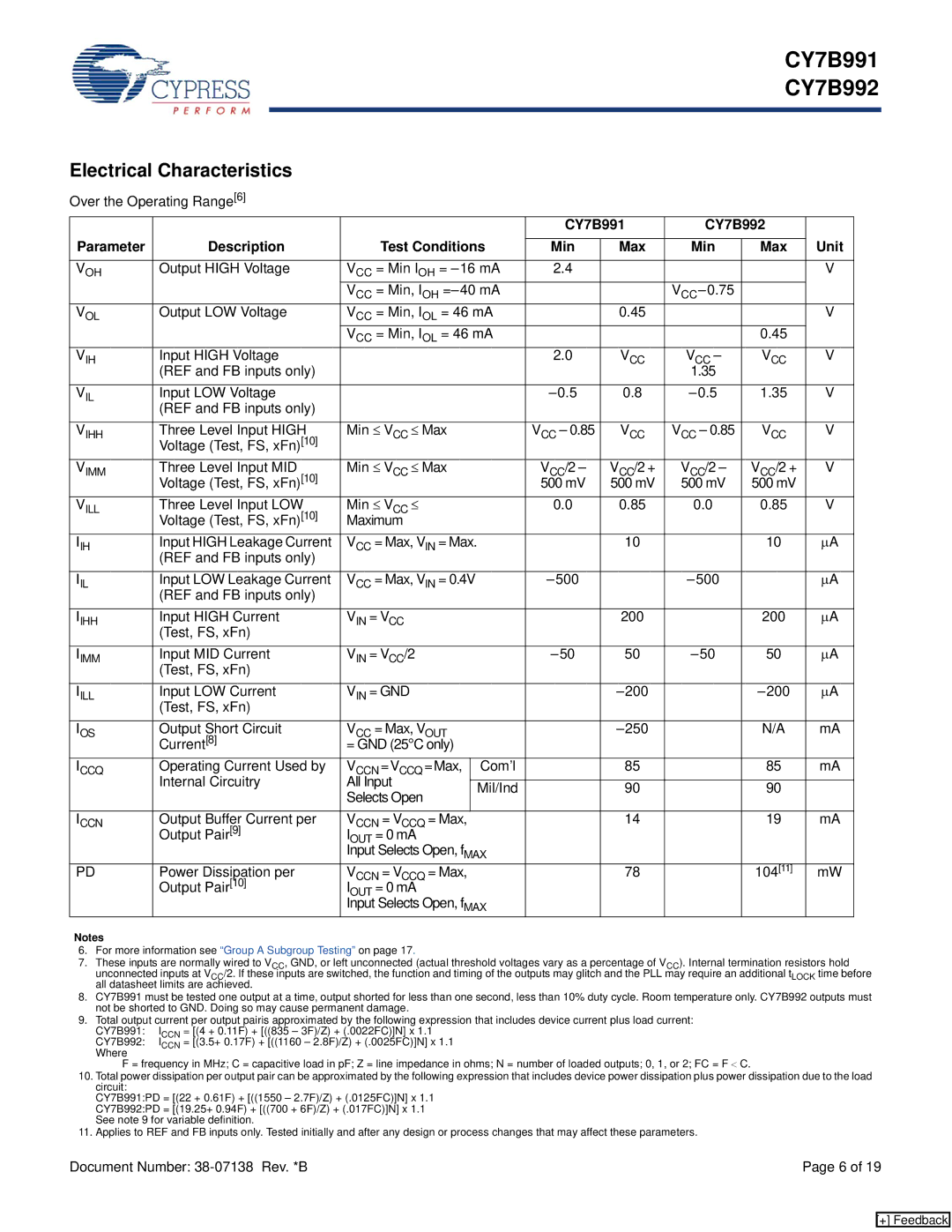
Electrical Characteristics

Over the Operating Range[6]


CY7B991

CY7B992


Parameter

Description


Test Conditions


Unit


Min

Max

Min

Max


VOH

Output HIGH Voltage

VCC = Min IOH = –16 mA

2.4


V


VCC = Min, IOH =–40 mA


VCC–0.75


VOL

Output LOW Voltage

VCC = Min, IOL = 46 mA


0.45


V


VCC = Min, IOL = 46 mA


0.45


VIH

Input HIGH Voltage


2.0

VCC

VCC

VCC

V


(REF and FB inputs only)


1.35


VIL

Input LOW Voltage


–0.5

0.8

–0.5

1.35

V


(REF and FB inputs only)


VIHH

Three Level Input HIGH

Min VCC Max


VCC – 0.85

VCC

VCC – 0.85

VCC

V


Voltage (Test, FS, xFn)[10]


VIMM

Three Level Input MID

Min VCC Max


VCC/2 –

VCC/2 +

VCC/2 –

VCC/2 +

V


Voltage (Test, FS, xFn)[10]


500 mV

500 mV

500 mV

500 mV


VILL

Three Level Input LOW

Min VCC


0.0

0.85

0.0

0.85

V


Voltage (Test, FS, xFn)[10]

Maximum


IIH

Input HIGH Leakage Current

VCC = Max, VIN = Max.


10


10

μA


(REF and FB inputs only)


IIL

Input LOW Leakage Current

VCC = Max, VIN = 0.4V


–500


–500


μA


(REF and FB inputs only)


IIHH

Input HIGH Current

VIN = VCC


200


200

μA


(Test, FS, xFn)


IIMM

Input MID Current

VIN = VCC/2


–50

50

–50

50

μA


(Test, FS, xFn)


IILL

Input LOW Current

VIN = GND


–200


–200

μA


(Test, FS, xFn)


IOS

Output Short Circuit

VCC = Max, VOUT


–250


N/A

mA


Current[8]

= GND (25°C only)


ICCQ

Operating Current Used by

VCCN

=VCCQ =Max,

Com’l


85


85

mA


Internal Circuitry

All Input


Mil/Ind


90


90


Selects Open


ICCN

Output Buffer Current per

VCCN

= VCCQ = Max,


14


19

mA


Output Pair[9]

IOUT = 0 mA


Input Selects Open, fMAX


PD

Power Dissipation per

V

CCN

= V = Max,


78


104[11]

mW


Output Pair[10]


CCQ


IOUT = 0 mA


Input Selects Open, fMAX


Notes

6.For more information see “Group A Subgroup Testing” on page 17.

7.These inputs are normally wired to VCC, GND, or left unconnected (actual threshold voltages vary as a percentage of VCC). Internal termination resistors hold unconnected inputs at VCC/2. If these inputs are switched, the function and timing of the outputs may glitch and the PLL may require an additional tLOCK time before all datasheet limits are achieved.

8.CY7B991 must be tested one output at a time, output shorted for less than one second, less than 10% duty cycle. Room temperature only. CY7B992 outputs must not be shorted to GND. Doing so may cause permanent damage.

9.Total output current per output pairis approximated by the following expression that includes device current plus load current: CY7B991: ICCN = [(4 + 0.11F) + [((835 – 3F)/Z) + (.0022FC)]N] x 1.1

CY7B992: ICCN = [(3.5+ 0.17F) + [((1160 – 2.8F)/Z) + (.0025FC)]N] x 1.1 Where

F = frequency in MHz; C = capacitive load in pF; Z = line impedance in ohms; N = number of loaded outputs; 0, 1, or 2; FC = F < C.

10.Total power dissipation per output pair can be approximated by the following expression that includes device power dissipation plus power dissipation due to the load circuit:

CY7B991:PD = [(22 + 0.61F) + [((1550 – 2.7F)/Z) + (.0125FC)]N] x 1.1 CY7B992:PD = [(19.25+ 0.94F) + [((700 + 6F)/Z) + (.017FC)]N] x 1.1 See note 9 for variable definition.

11.Applies to REF and FB inputs only. Tested initially and after any design or process changes that may affect these parameters.

Document Number: 38-07138 Rev. *B

Page 6 of 19

[+] Feedback

Page 6
Image 6
Cypress CY7B992, CY7B991 manual Electrical Characteristics

CY7B991, CY7B992 specifications

The Cypress CY7B992 and CY7B991 are advanced synchronous SRAM devices designed for high-speed applications, particularly in the field of telecommunications, networking, and high-performance computing. These SRAMs are notable for their ability to operate at high frequencies, making them suitable for systems that require rapid data access and processing.

One of the main features of the CY7B992 and CY7B991 is their support for synchronous operation, which allows for data transfers aligned with a clock signal. This capability significantly enhances performance by reducing access times and increasing data throughput compared to traditional asynchronous SRAMs. With their optimized write and read cycles, these devices can achieve low latency, enabling efficient data handling in real-time applications.

Another key technology utilized in these devices is the use of a 2-port architecture, which supports simultaneous read and write operations. This dual-port design allows for greater flexibility and efficiency in data management, making it easier to implement complex memory architectures in various applications. The architecture also supports burst mode operation, allowing for rapid sequential data access, which is crucial in environments where speed is paramount.

The CY7B992 and CY7B991 feature a wide data bus width, accommodating 32 bits to suit modern data processing needs. Their compact size and ease of integration into existing systems make them popular choices among designers and engineers. Moreover, these SRAMs offer a comprehensive range of voltage and temperature specifications, ensuring reliable performance across diverse operating conditions.

In terms of power management, the CY7B992 and CY7B991 are designed to consume low power while maintaining high performance, making them ideal for battery-operated or energy-sensitive applications. The devices include various power-saving features, such as power-down modes, enabling users to reduce overall system power consumption when the memory is not actively in use.

Overall, the Cypress CY7B992 and CY7B991 are robust, high-speed SRAM solutions that cater to the demands of sophisticated, data-intensive applications. Their synchronous operation, dual-port architecture, and efficient power management characteristics make them essential components in modern electronic systems. As technology continues to evolve, these SRAMs are poised to play a critical role in advancing the capabilities of next-generation devices.