CY7C1166V18, CY7C1177V18
CY7C1168V18, CY7C1170V18
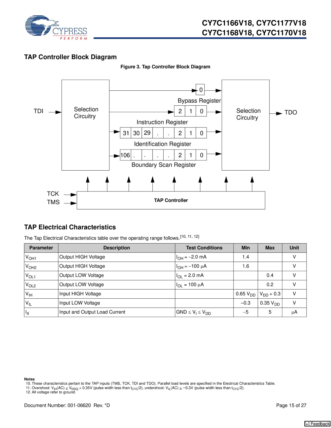
TAP Controller Block Diagram
Figure 3. Tap Controller Block Diagram
TDI
|
|
|
|
| 0 |
|
|
|
|
| Bypass Register |
|
| ||
Selection |
|
| 2 | 1 | 0 | Selection | TDO |
Circuitry | Instruction Register |
|
| Circuitry |
| ||
|
|
|
|
| |||
31 | 30 29 . . | 2 | 1 | 0 |
|
| |
| Identification Register |
|
|
| |||
106 | . . | . . | 2 | 1 | 0 |
|
|
| Boundary Scan Register |
|
|
| |||
TCK TMS
TAP Controller
TAP Electrical Characteristics
The Tap Electrical Characteristics table over the operating range follows.[10, 11, 12]
Parameter | Description | Test Conditions | Min | Max | Unit |
VOH1 | Output HIGH Voltage | IOH = −2.0 mA | 1.4 |
| V |
VOH2 | Output HIGH Voltage | IOH = −100 μA | 1.6 |
| V |
VOL1 | Output LOW Voltage | IOL = 2.0 mA |
| 0.4 | V |
VOL2 | Output LOW Voltage | IOL = 100 μA |
| 0.2 | V |
VIH | Input HIGH Voltage |
| 0.65 VDD | VDD + 0.3 | V |
VIL | Input LOW Voltage |
| 0.35 VDD | V | |
IX | Input and Output Load Current | GND ≤ VI ≤ VDD | −5 | 5 | μA |
Notes
10.These characteristics pertain to the TAP inputs (TMS, TCK, TDI and TDO). Parallel load levels are specified in the Electrical Characteristics Table.
11.Overshoot: VIH(AC) < VDDQ + 0.35V (pulse width less than tCYC/2), undershoot: VIL(AC) > −0.3V (pulse width less than tCYC/2).
12.All voltage refer to ground.
Document Number: | Page 15 of 27 |
[+] Feedback