DES-1008M User’s Guide
Refer to the Indicator Panel section (below) to identify the different status indicators and scales.
♦Slots 1 to 4
Support the slide-in port modules. Each module provides two switched ports for maximum system configuration of eight switched ports. Depending on the installed modules, port types can vary from ordinary twisted-pair ports to BNC or fiber-optic ports. The base unit does not include any slide-in port modules to provide users the freedom to choose their system’s port configuration.
For the list of supported slide-in port modules and their respective specifications, see Appendix C, Slide-in Port Modules. For information on module installation, see the Port Module Installation section of Chapter 3, Installation.
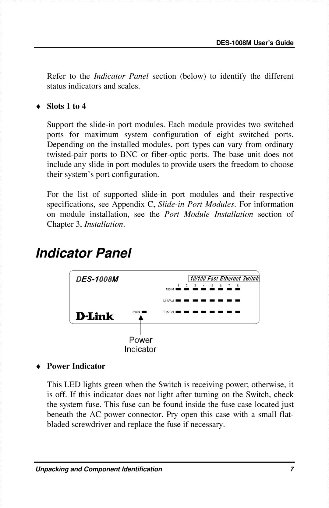
Indicator Panel
♦Power Indicator
This LED lights green when the Switch is receiving power; otherwise, it is off. If this indicator does not light after turning on the Switch, check the system fuse. This fuse can be found inside the fuse case located just beneath the AC power connector. Pry open this case with a small flat- bladed screwdriver and replace the fuse if necessary.
Unpacking and Component Identification | 7 |