10/100 NWay Ethernet/Fast Ethernet Switch User’s Guide
Rear Panel
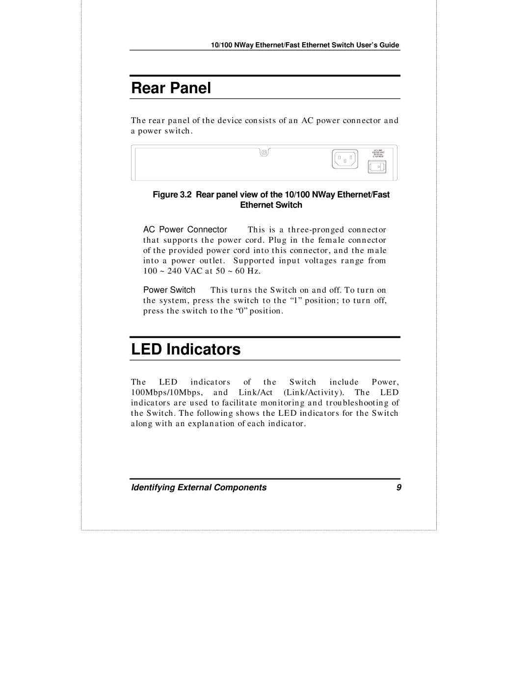
The rear panel of the device consists of an AC power connector and a power switch.
Figure 3.2 Rear panel view of the 10/100 NWay Ethernet/Fast
Ethernet Switch
♦AC Power Connector This is a
♦Power Switch This turns the Switch on and off. To turn on the system, press the switch to the “1” position; to turn off, press the switch to the “0” position.
LED Indicators
The LED indicators of the Switch include Power, 100Mbps/10Mbps, and Link/Act (Link/Activity). The LED indicators are used to facilitate monitoring and troubleshooting of the Switch. The following shows the LED indicators for the Switch along with an explanation of each indicator.
Identifying External Components | 9 |