EXPLODED VIEW AND PARTS LIST
1.DOOR ASSEMBLY
Refer to Disassembly and assembly.
2.CONTROL PANEL ASSEMBLY Refer to Disassembly and assembly.
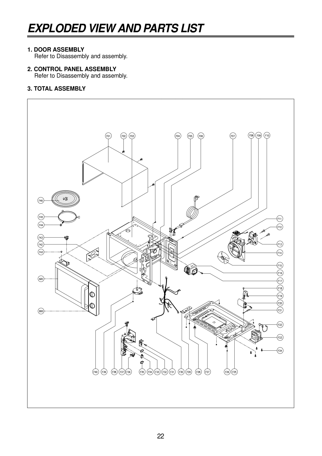
3.TOTAL ASSEMBLY
22 |
Refer to Disassembly and assembly.
2.CONTROL PANEL ASSEMBLY Refer to Disassembly and assembly.
22 |