Manuals
/
Daewoo
/
Kitchen Appliance
/
Microwave Oven
Daewoo
KOR-6N575S, Microwave Oven
service manual
External View, Outer Dimension
Models:
KOR-6N575S
Microwave Oven
1
5
26
26
Download
26 pages
12.42 Kb
1
2
3
4
5
6
7
8
Troubleshooting
Specifications
Install
Parts list
Feature Diagram
Dimension
Disassembly and Assembly
Procedure
Adjustment
Safety and Precautions
Page 5
Image 5
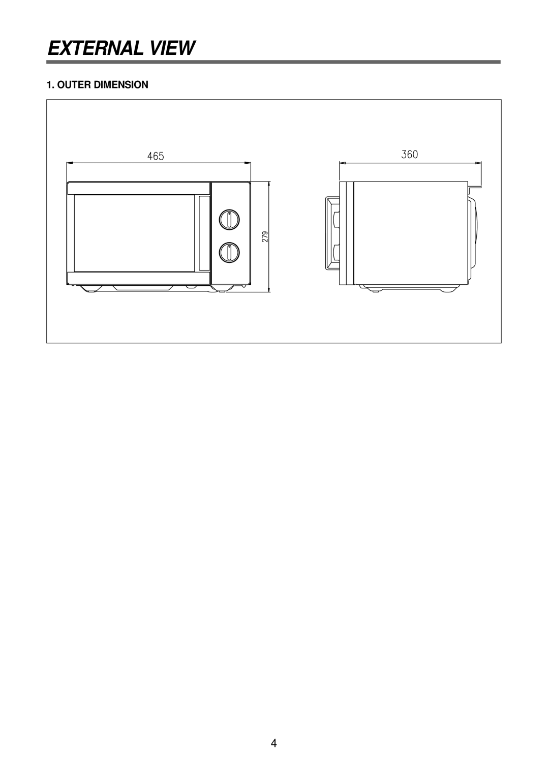
EXTERNAL VIEW
1. OUTER DIMENSION
4
Page 4
Page 6
Page 5
Image 5
Page 4
Page 6
Contents
Microwave Oven
Table of Contents
For Safe Operation
Safety and Precautions
KOR-6N575S
Specifications
External View
Outer Dimension
Safety interlock system
Feature Diagram
Leave space behind and side
Installation
Operations and Functions
Variable power cooking
Disassembly and Assembly
To remove cabinet
To remove door assembly
REF no Part Code Part Name Description ’TY
To remove door parts
Page
QTY
To remove control panel parts
To remove high voltage capacitor
High voltage circuit wiring To remove magnetron
To remove H.V.transformer
To remove wind guide assembly
Adjustment
Interlock Mechanism and Adjustment
Trouble 1 Door shut, timer set, but no cooking takes place
Troubleshooting Guide
YES
Measurement and Test
Measurement of the Microwave Power Output
Procedure
Microwave Radiation Test
Procedures
High voltage transformer
Component Test Procedure
Wiring Diagram
Total Assembly
Exploded View and Parts List
Door Assembly
Name Part Code Part Name Description QTY
Daewoo Electronics Corp
About this Manual
Top
Page
Image
Contents