Improved Checksum Calculation With Devices Using Sector Protect
This change only affects filling the programmer RAM with “FF” before you program a 16-bit device. In versions of software before V5.9, if you entered sector protect data, only the least significant byte of the 16-bit word in RAM was changed. For example, if you entered sector protect data “01”, the 16-bit word would read “FF01”. All sectors were protected correctly but a different device checksum was calculated because the “FF” in the most significant byte (“FF01”) was added into the device checksum. In software version 5.9 and later, when you enter sector protect data “01”, the 16-bit word in the programmer’s RAM will be entered as “0001”. This modification was made so the high order byte does not change the device checksum reported at the end of the programming cycle.
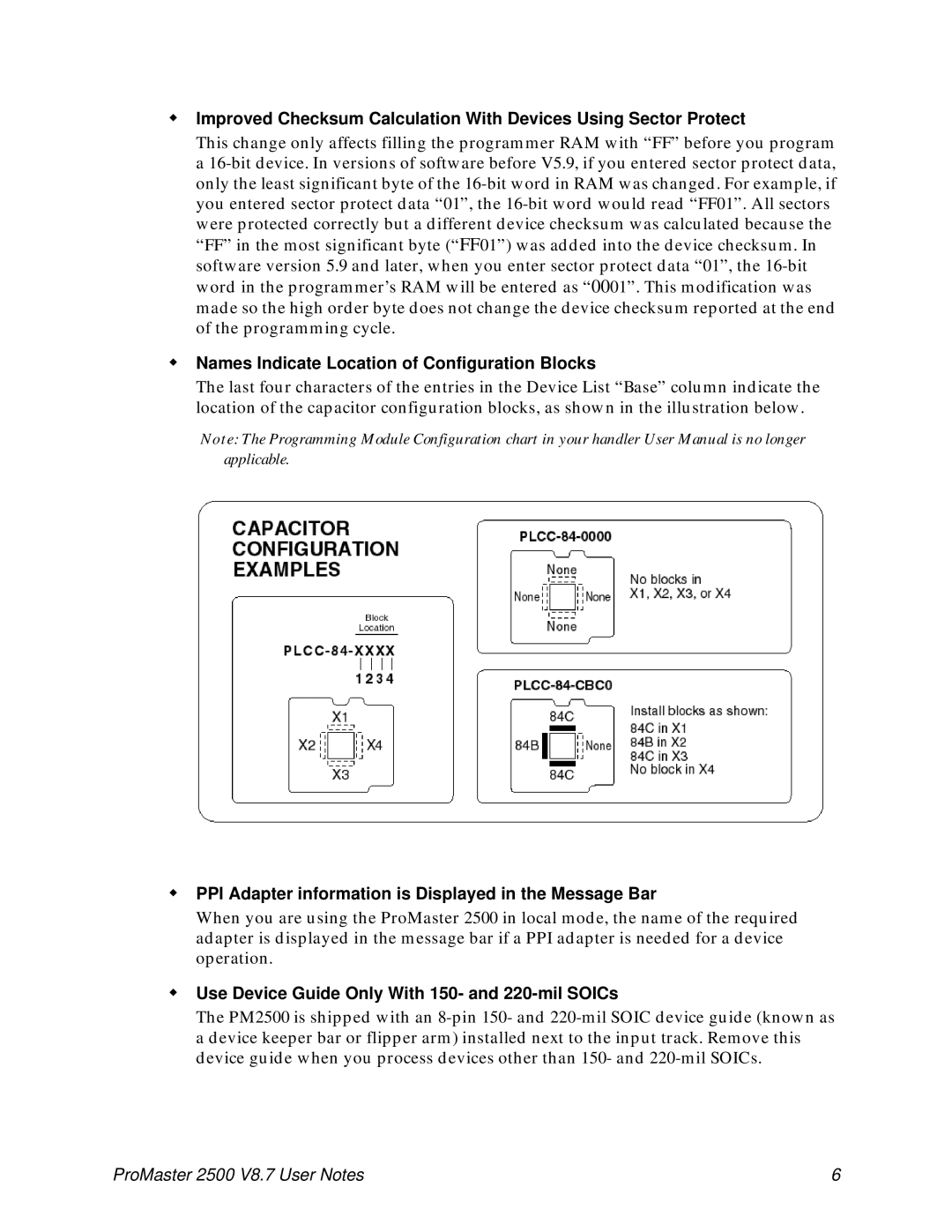
Names Indicate Location of Configuration Blocks
The last four characters of the entries in the Device List “Base” column indicate the location of the capacitor configuration blocks, as shown in the illustration below.
Note: The Programming Module Configuration chart in your handler User Manual is no longer applicable.
PPI Adapter information is Displayed in the Message Bar
When you are using the ProMaster 2500 in local mode, the name of the required adapter is displayed in the message bar if a PPI adapter is needed for a device operation.
Use Device Guide Only With 150- and 220-mil SOICs
The PM2500 is shipped with an 8-pin 150- and 220-mil SOIC device guide (known as a device keeper bar or flipper arm) installed next to the input track. Remove this device guide when you process devices other than 150- and 220-mil SOICs.
ProMaster 2500 V8.7 User Notes | 6 |