386 | Type IV™ White Paper | Appendix C |
Enter the dbx Type IV™ Conversion System. Like its related predecessor
The dbx Type IV™ Conversion System combines proprietary analog and digital processing techniques to cap- ture a much wider dynamic range than the A/D converter could by itself, preserving the maximum amount of informa- tion from the analog signal. This information is then encoded within the available bits of whichever A/D converter is used. This means that Type IV™ improves the performance of any A/D converter, from
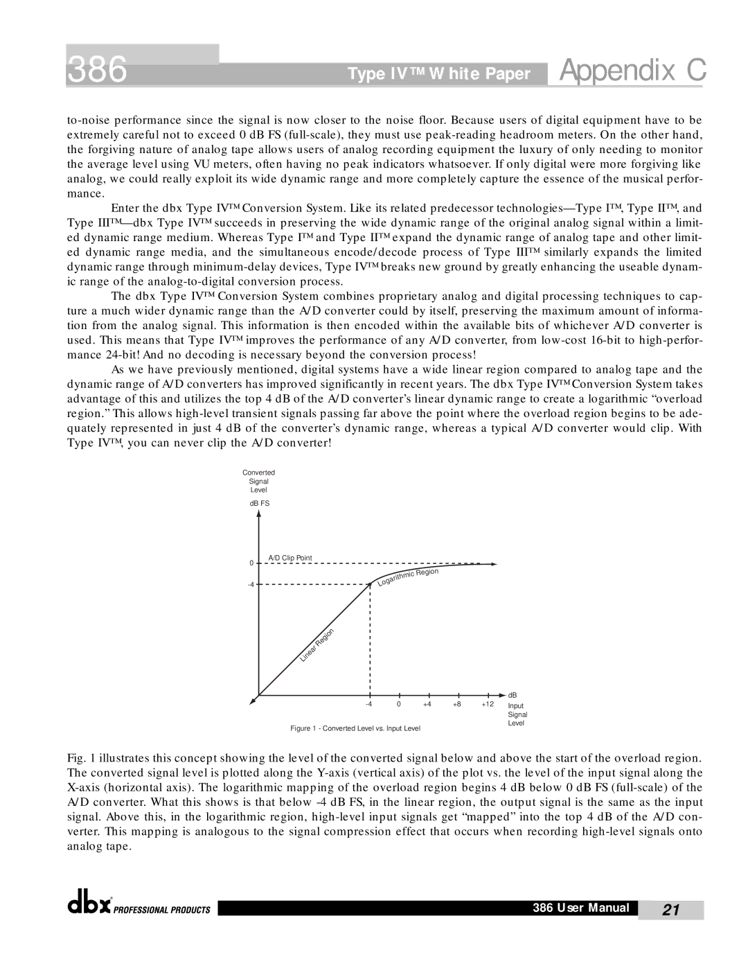
As we have previously mentioned, digital systems have a wide linear region compared to analog tape and the dynamic range of A/D converters has improved significantly in recent years. The dbx Type IV™ Conversion System takes advantage of this and utilizes the top 4 dB of the A/D converter’s linear dynamic range to create a logarithmic “overload region.” This allows
Converted
Signal
Level
dB FS
A/D Clip Point
0
|
|
|
|
| ic |
|
|
|
| hm | |
|
|
| rit |
| |
|
| a |
|
| |
| g |
|
|
| |
o |
|
|
|
| |
L |
|
|
|
|
|
Region
Linear | Region |
|
|
|
|
|
|
|
|
|
| dB |
|
|
|
|
|
|
|
|
| |
0 | +4 | +8 | +12 | Input | |||||
|
|
|
|
|
|
|
|
| Signal |
|
|
|
|
|
|
|
|
| Level |
Figure 1 - Converted Level vs. Input Level
Fig. 1 illustrates this concept showing the level of the converted signal below and above the start of the overload region. The converted signal level is plotted along the Y-axis (vertical axis) of the plot vs. the level of the input signal along the X-axis (horizontal axis). The logarithmic mapping of the overload region begins 4 dB below 0 dB FS (full-scale) of the A/D converter. What this shows is that below -4 dB FS, in the linear region, the output signal is the same as the input signal. Above this, in the logarithmic region, high-level input signals get “mapped” into the top 4 dB of the A/D con- verter. This mapping is analogous to the signal compression effect that occurs when recording high-level signals onto analog tape.
®
386 User Manual | 21 |
|
|
