1.Connect the top
2.Connect the bottom
3.Lay the display panel in the top cover.
4.Route the
5.Replace the four M2 x
6.Replace the display bezel.
Display Latch Assembly
Removing the Display Latch Assembly
CAUTION: Before performing the following procedures, read the safety instructions in your Owner's Manual.
CAUTION: To prevent static damage to components inside your computer, discharge static electricity from your body before you touch any of your computer's electronic components. You can do so by touching an unpainted metal surface.
1.Follow the instructions in "Before Working Inside Your Computer."
2.Remove the keyboard.
3.Remove the display assembly.
4.Remove the display bezel.
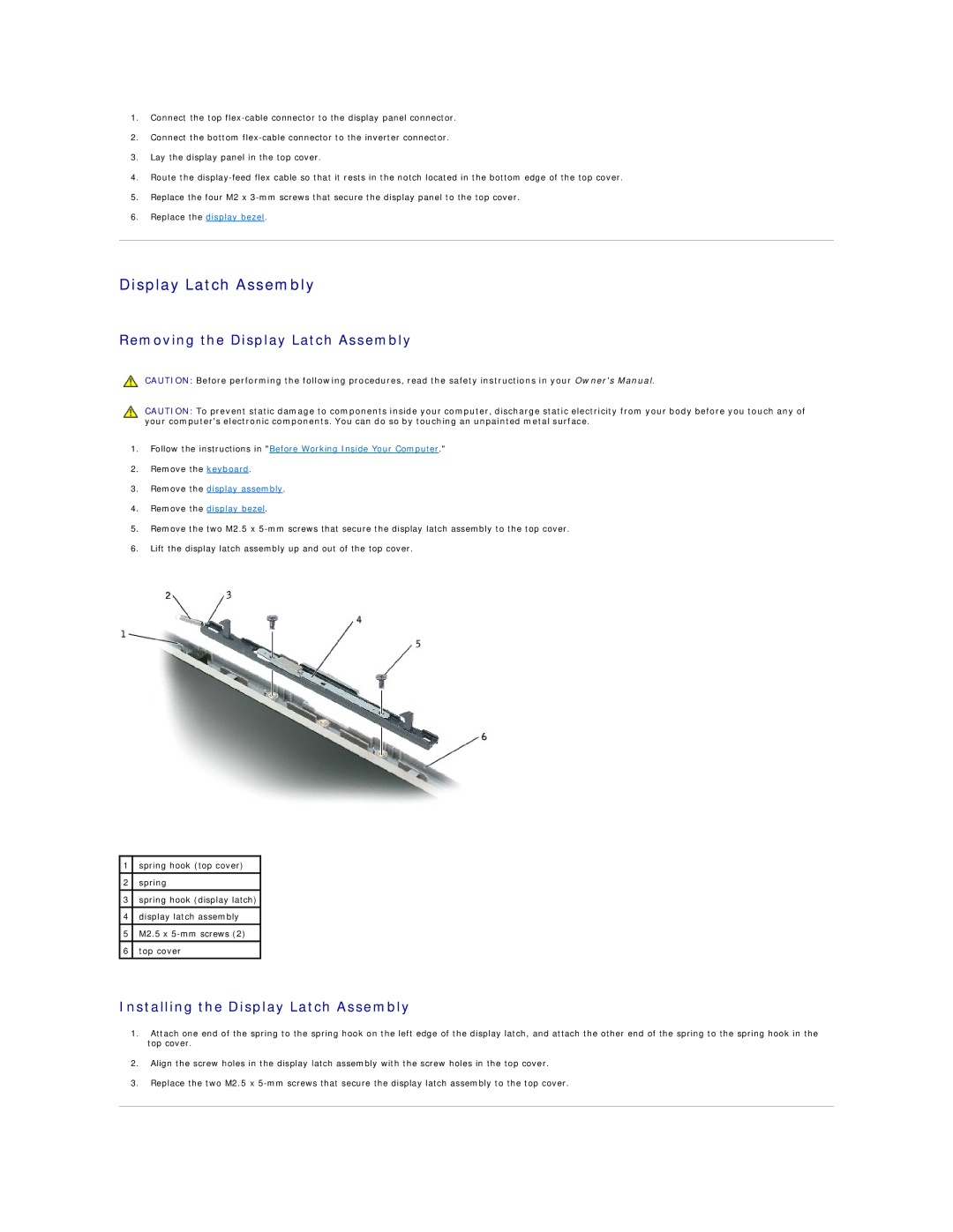
5.Remove the two M2.5 x
6.Lift the display latch assembly up and out of the top cover.
1 | spring hook (top cover) |
|
|
2 | spring |
|
|
3 | spring hook (display latch) |
|
|
4 | display latch assembly |
|
|
5 | M2.5 x |
|
|
6 | top cover |
|
|
Installing the Display Latch Assembly
1.Attach one end of the spring to the spring hook on the left edge of the display latch, and attach the other end of the spring to the spring hook in the top cover.
2.Align the screw holes in the display latch assembly with the screw holes in the top cover.
3.Replace the two M2.5 x