3.Disconnect the processor fan cable from the CPU_FAN connector on the system board (see System Board Components).
4.Carefully move away any cables that are routed over the processor fan and heat sink assembly.
5.Follow the instructions below to replace the processory fan and heat sink assembly, depending on your computer model:
Inspiron 518
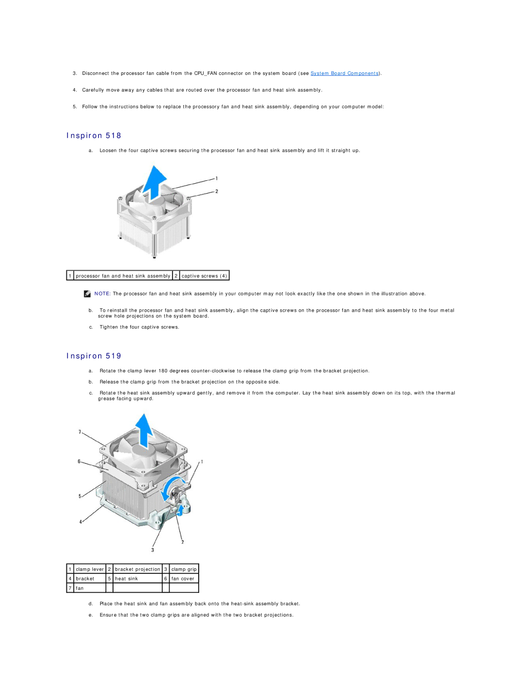
a.Loosen the four captive screws securing the processor fan and heat sink assembly and lift it straight up.
![]() 1
1 ![]() processor fan and heat sink assembly
processor fan and heat sink assembly ![]() 2
2 ![]() captive screws (4)
captive screws (4) ![]()
NOTE: The processor fan and heat sink assembly in your computer may not look exactly like the one shown in the illustration above.
b.To reinstall the processor fan and heat sink assembly, align the captive screws on the processor fan and heat sink assembly to the four metal screw hole projections on the system board.
c.Tighten the four captive screws.
Inspiron 519
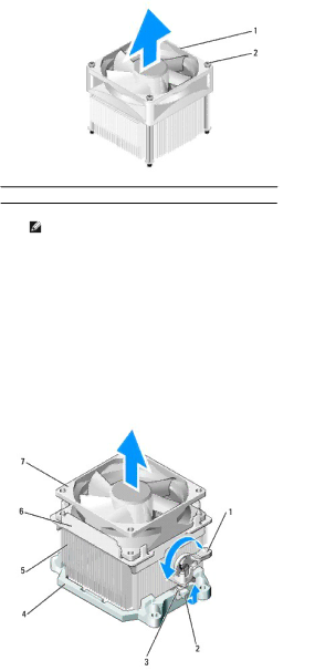
a.Rotate the clamp lever 180 degrees
b.Release the clamp grip from the bracket projection on the opposite side.
c.Rotate the heat sink assembly upward gently, and remove it from the computer. Lay the heat sink assembly down on its top, with the thermal grease facing upward.
1 | clamp lever | 2 | bracket projection | 3 | clamp grip |
4 | bracket | 5 | heat sink | 6 | fan cover |
|
|
|
|
|
|
7 | fan |
|
|
|
|
|
|
|
|
|
|
d.Place the heat sink and fan assembly back onto the
e.Ensure that the two clamp grips are aligned with the two bracket projections.