switch all packets to the core. Data leaving the stack of Edge Switch 1 with a destination address at Edge Switch 2 would not have to take the additional hops of going to the core of the network and then back out to Edge Switch 2.
In this scenario, the aggregation switch can actually run multiple links to the network core and to the edge switches to provide faster connectivity. Edge Switch 1 consists of three stacked PowerConnect 3348s that are linked together via their stacking modules. One uplink is connected to the first PowerConnect 6024F at the top of the stack, while a second uplink is connected to the redundant PowerConnect 6024 F. This creates multiple data paths to the core, providing high availability of the network data. Edge Switch 2 is similar except the switches are cascaded to each other via their Gigabit ports. Multiple Spanning Tree protocol on the PowerConnect 6024 switches is enabled to help prevent a broadcast storm. RIP or OSPF routing can be enabled to route data between these subnets.
Application benefits include:
-High bandwidth network from the desktop to the core
-Resilient and
-
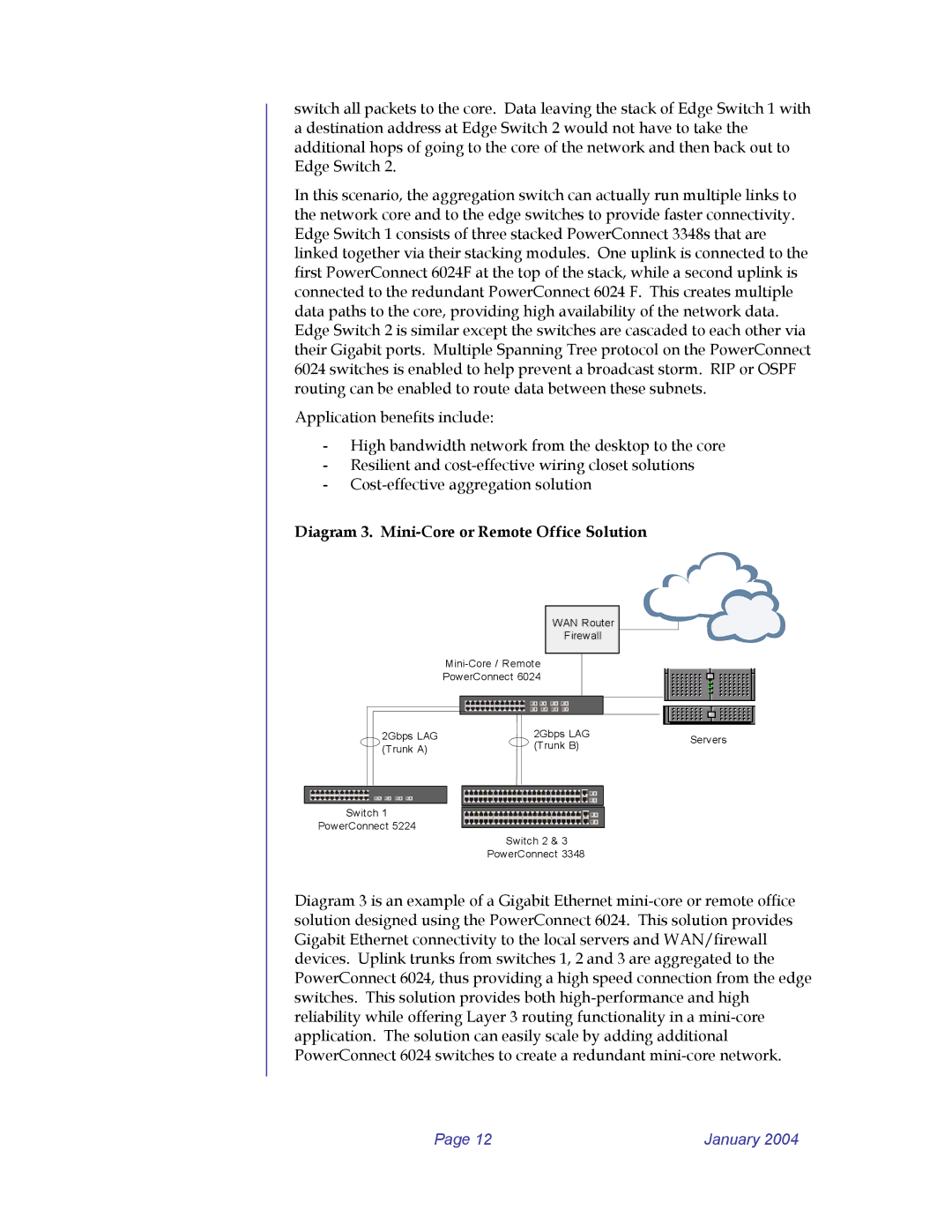
Diagram 3. Mini-Core or Remote Office Solution
|
|
|
|
|
| WAN Router |
|
| ||
|
|
|
|
|
| Firewall |
|
| ||
|
|
|
|
|
|
|
|
| ||
|
|
|
|
|
|
| ||||
|
|
| PowerConnect 6024 |
|
|
|
| |||
|
|
|
|
|
|
|
|
|
|
|
|
|
|
|
|
|
|
|
|
|
|
|
|
|
|
|
|
|
|
| ||
|
| 2Gbps LAG |
|
| 2Gbps LAG | Servers | ||||
|
| (Trunk A) |
|
| (Trunk B) | |||||
|
|
|
|
|
| |||||
|
|
|
|
|
|
|
|
|
| |
|
|
|
|
|
|
|
|
|
|
|
|
|
|
|
|
|
|
|
|
|
|
|
|
|
|
|
|
|
|
|
|
|
Switch 1
PowerConnect 5224
Switch 2 & 3
PowerConnect 3348
Diagram 3 is an example of a Gigabit Ethernet
Page 12 | January 2004 |
