![]() Video
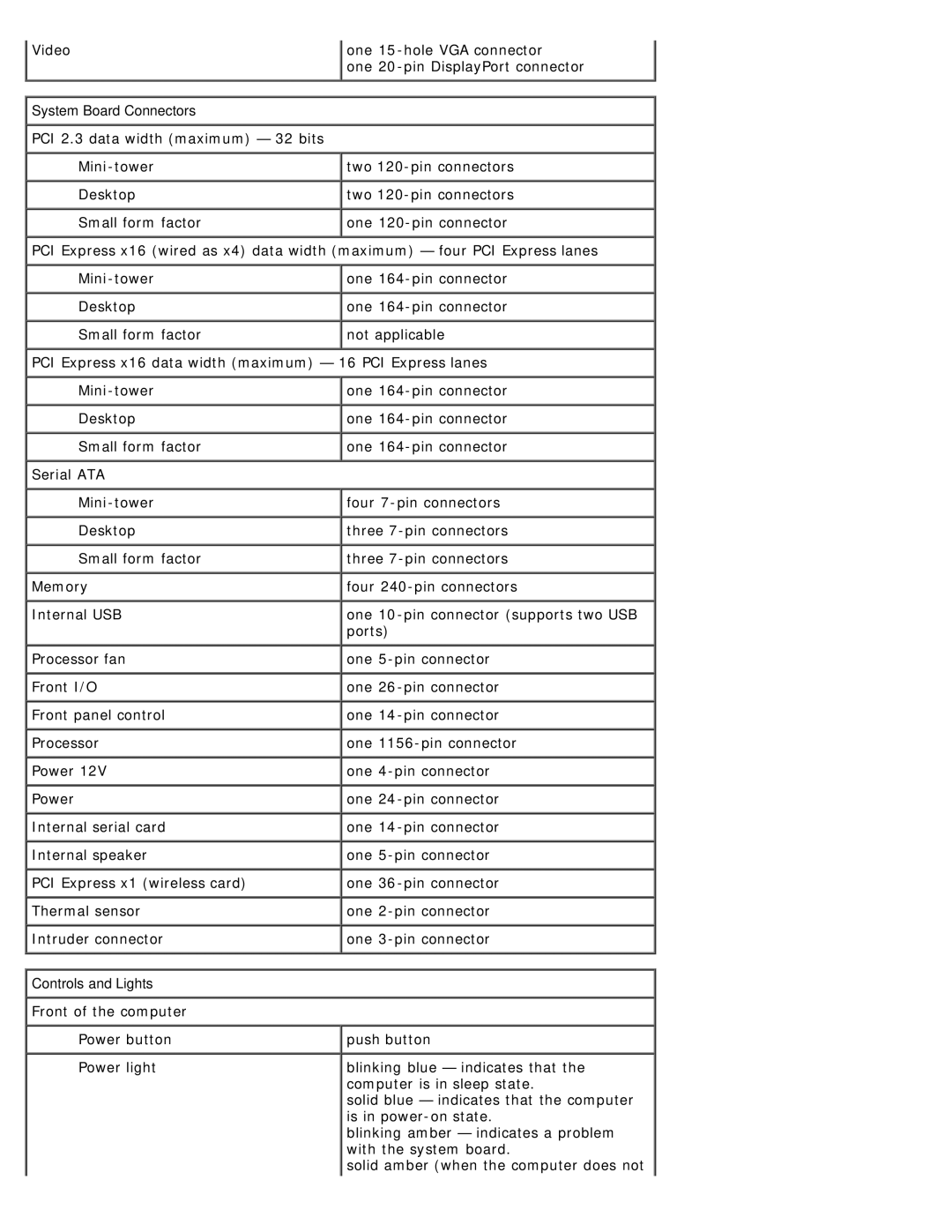
Video
one
one
System Board Connectors |
|
PCI 2.3 data width (maximum) — 32 bits |
|
two | |
Desktop | two |
Small form factor | one |
PCI Express x16 (wired as x4) data width (maximum) — four PCI Express lanes | |
one | |
Desktop | one |
Small form factor | not applicable |
PCI Express x16 data width (maximum) — 16 PCI Express lanes | |
one | |
Desktop | one |
Small form factor | one |
Serial ATA |
|
four | |
Desktop | three |
Small form factor | three |
Memory | four |
Internal USB | one |
| ports) |
Processor fan | one |
Front I/O | one |
Front panel control | one |
Processor | one |
Power 12V | one |
Power | one |
Internal serial card | one |
Internal speaker | one |
PCI Express x1 (wireless card) | one |
Thermal sensor | one |
Intruder connector | one |
Controls and Lights |
|
Front of the computer |
|
Power button | push button |
Power light | blinking blue — indicates that the |
| computer is in sleep state. |
| solid blue — indicates that the computer |
| is in |
| blinking amber — indicates a problem |
| with the system board. |
| solid amber (when the computer does not |