Manuals
/
Dell
/
Computer Equipment
/
Computer Hardware
Dell
PCI3 main power input, diskette-drive, connector POWER1, interface connector, Floppy, Serial
Models:
PCI3
1
2
20
20
Download
20 pages
63.83 Kb
1
2
3
4
5
6
7
8
access indicator
battery BATTERY socket
Page 2
Image 2
Page 1
Page 3
Page 2
Image 2
Page 1
Page 3
Contents
Installing System Board Options
This chapter describes how to install the following options
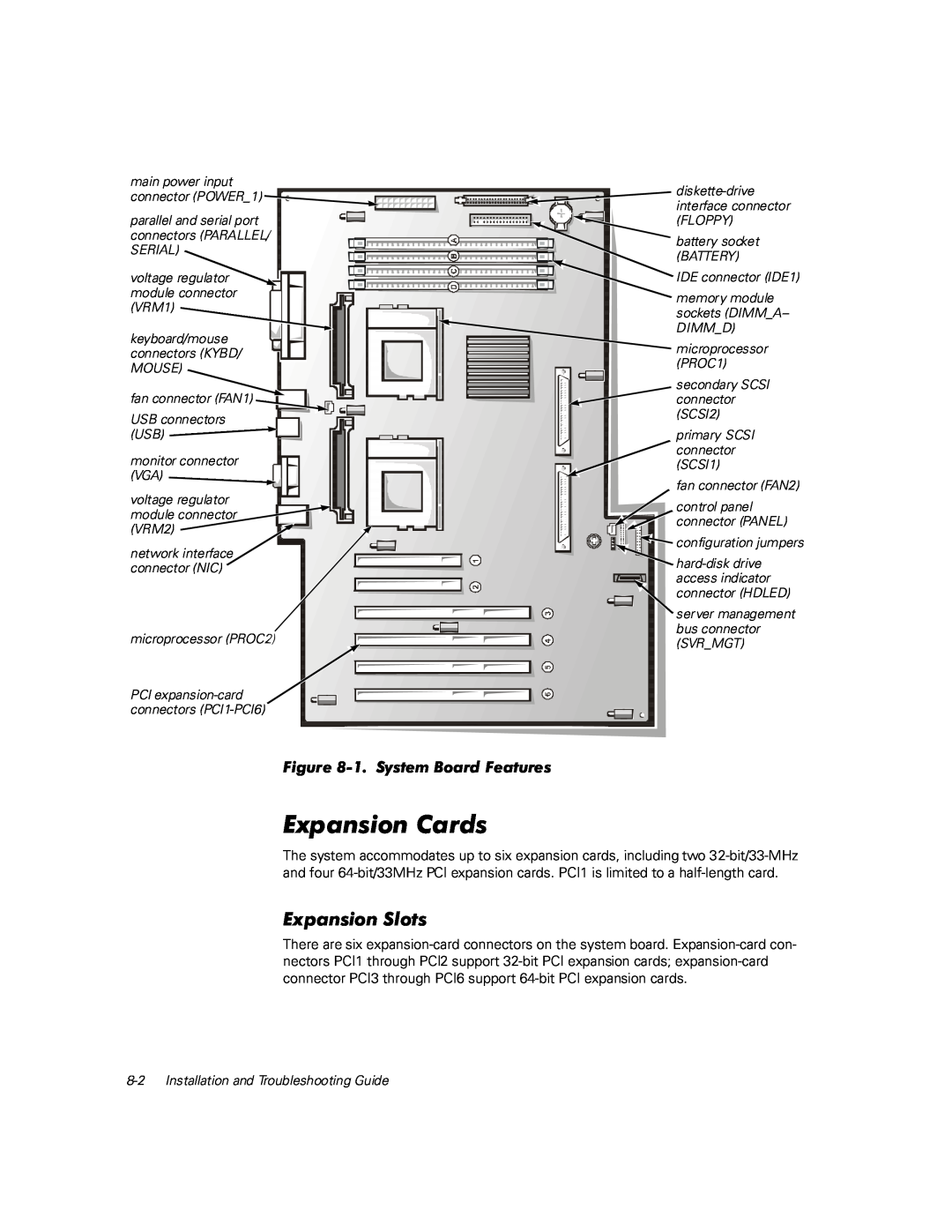
Use Figure 8-1 to locate the system board features
Peripheral Component Interconnect PCI expansion cards System memory
interface connector
main power input
connector POWER1
connectors PARALLEL
Follow this general procedure to install an expansion card
3. Unlatch the card guide as shown in Figure
4. Insert the expansion card into the expansion-card connector
8-4 Installation and Troubleshooting Guide
unlatching card guide
Page
Follow this general procedure to remove an expansion card
computer
memory module socket
front of
8-8 Installation and Troubleshooting Guide
Use the following procedure to install a memory module see Figure
The following items are included in the microprocessor upgrade kit
1. Remove the computer cover according to the instructions in “Removing the Computer Cover,” in Chapter
5. Remove the heat sink
Page
9. Install the microprocessor chip in the socket see Figure
VRM socket VRM latches
securing clip heat sink microprocessor chip
socket
microprocessor
13. Connect the FAN1 connector 14. Replace the air shroud
Strike the F1 key to continue F2 to run the setup utility
Time-of-day not set - please run SETUP program
Invalid configuration information - please run SETUP program
battery BATTERY socket
8-18 Installation and Troubleshooting Guide
10. Turn off your computer, and unplug it for at least 10 minutes
8-20 Installation and Troubleshooting Guide
Top
Page
Image
Contents