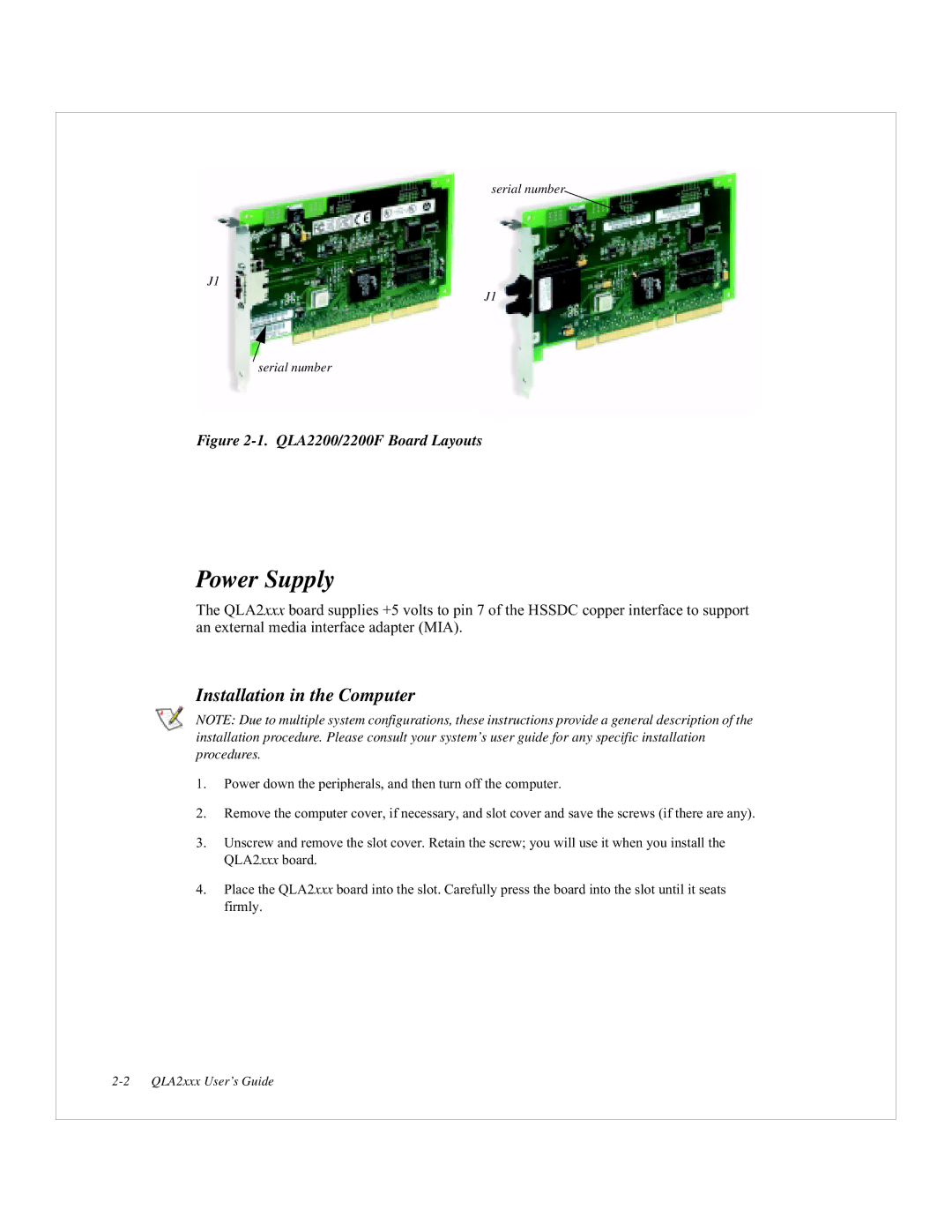
serial number
J1
J1
serial number
Figure 2-1. QLA2200/2200F Board Layouts
Power Supply
The QLA2xxx board supplies +5 volts to pin 7 of the HSSDC copper interface to support an external media interface adapter (MIA).
Installation in the Computer
NOTE: Due to multiple system configurations, these instructions provide a general description of the installation procedure. Please consult your system’s user guide for any specific installation procedures.
1.Power down the peripherals, and then turn off the computer.
2.Remove the computer cover, if necessary, and slot cover and save the screws (if there are any).
3.Unscrew and remove the slot cover. Retain the screw; you will use it when you install the QLA2xxx board.
4.Place the QLA2xxx board into the slot. Carefully press the board into the slot until it seats firmly.