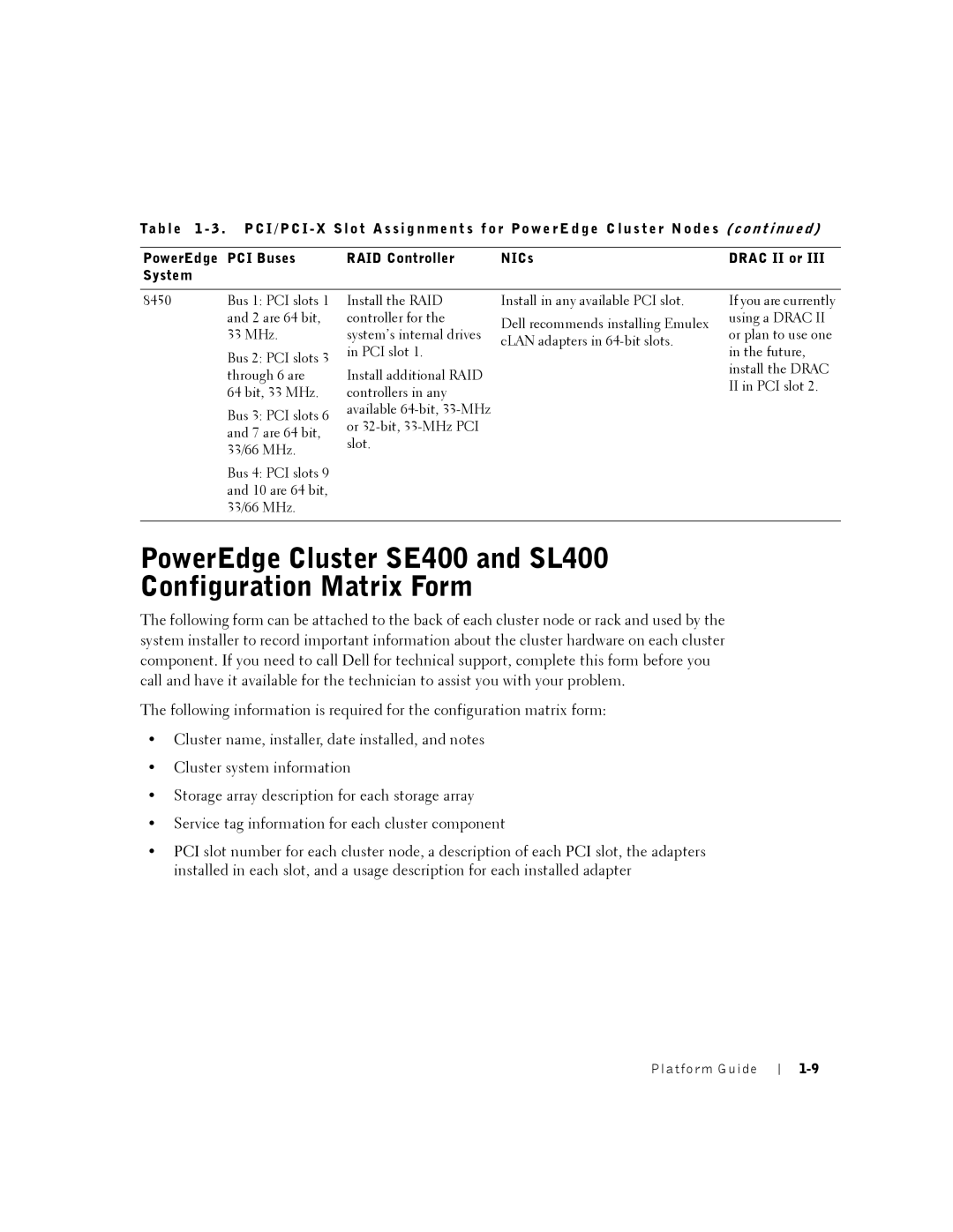
Ta b l e 1 - 3 . P C I / P C I - X S l o t A s s i g n m e n t s f o r Po w e r E d g e C l u s t e r N o d e s ( c o n t in u e d )
PowerEdge PCI Buses | RAID Controller | NICs | DRAC II or III |
System |
|
|
|
8450 | Bus 1: PCI slots 1 |
| and 2 are 64 bit, |
| 33 MHz. |
Bus 2: PCI slots 3 through 6 are
64 bit, 33 MHz.
Bus 3: PCI slots 6 and 7 are 64 bit, 33/66 MHz.
Bus 4: PCI slots 9 and 10 are 64 bit, 33/66 MHz.
Install the RAID controller for the system’s internal drives in PCI slot 1.
Install additional RAID controllers in any available
Install in any available PCI slot.
Dell recommends installing Emulex cLAN adapters in
If you are currently using a DRAC II or plan to use one in the future, install the DRAC II in PCI slot 2.
PowerEdge Cluster SE400 and SL400 Configuration Matrix Form
The following form can be attached to the back of each cluster node or rack and used by the system installer to record important information about the cluster hardware on each cluster component. If you need to call Dell for technical support, complete this form before you call and have it available for the technician to assist you with your problem.
The following information is required for the configuration matrix form:
•Cluster name, installer, date installed, and notes
•Cluster system information
•Storage array description for each storage array
•Service tag information for each cluster component
•PCI slot number for each cluster node, a description of each PCI slot, the adapters installed in each slot, and a usage description for each installed adapter