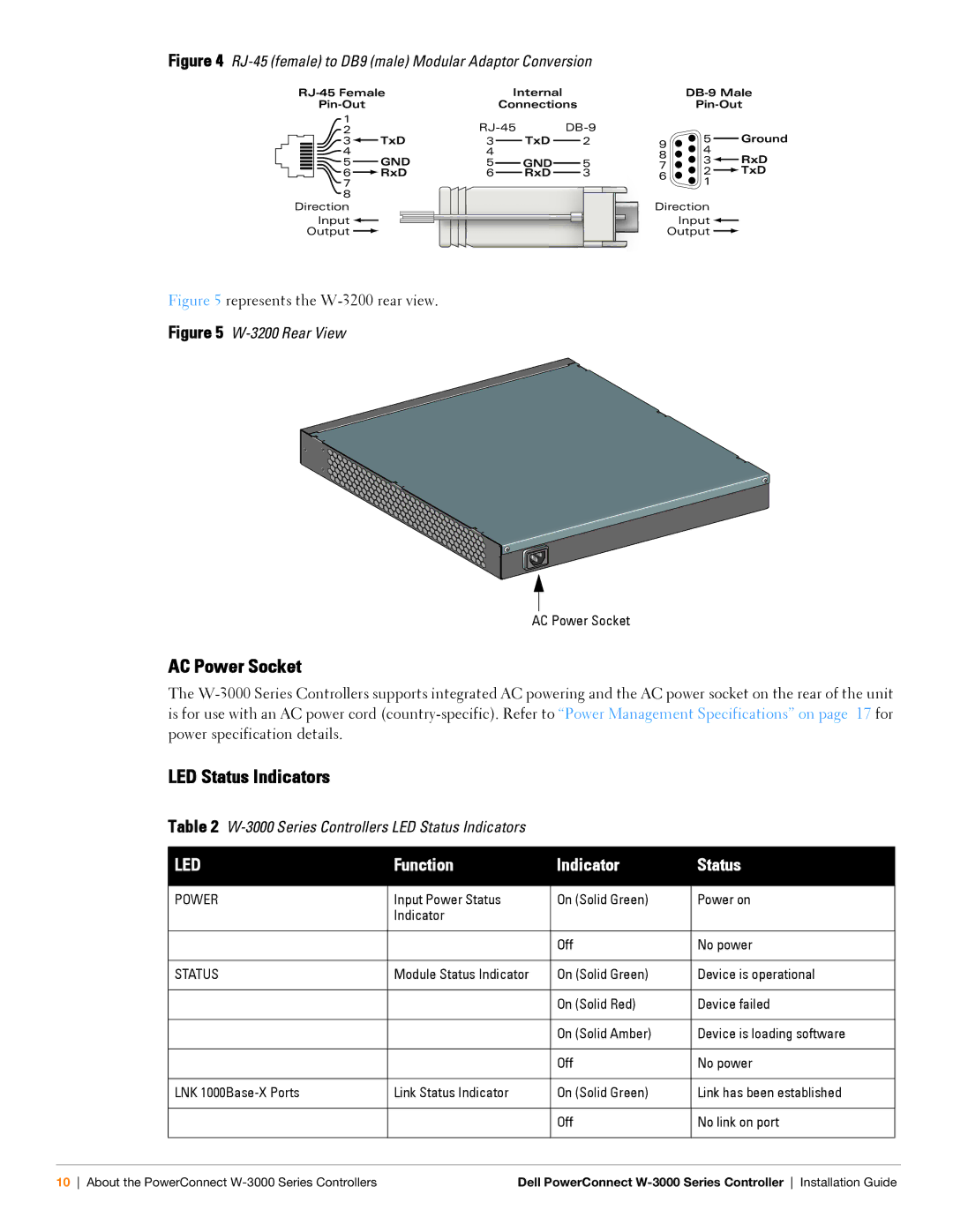
Figure 4 RJ-45 (female) to DB9 (male) Modular Adaptor Conversion
|
| Internal |
|
|
| |||||||||||||||||||||
|
|
|
|
|
|
|
| Connections |
| |||||||||||||||||
1 |
|
|
|
|
|
|
|
|
|
|
|
|
|
|
|
| ||||||||||
2 |
|
|
|
|
|
|
|
|
|
| 5 |
|
|
|
| Ground | ||||||||||
|
| 3 |
|
|
|
|
|
| TxD | 3 |
|
|
| TxD |
|
| 2 | 9 |
|
|
|
| ||||
|
|
|
|
|
|
|
|
|
|
|
|
|
|
|
|
| ||||||||||
|
|
|
|
|
|
| ||||||||||||||||||||
|
| 4 |
|
|
|
|
|
|
|
|
| 4 |
|
|
|
|
|
|
| 4 |
|
|
|
|
| |
|
|
|
|
|
|
|
|
|
|
|
|
|
|
|
|
|
| 8 |
|
|
|
| RxD | |||
|
|
|
|
|
|
|
|
|
|
|
|
|
|
|
| |||||||||||
|
| 5 |
|
|
|
|
|
| GND | 5 |
|
|
| GND |
|
| 5 | 3 |
|
|
|
| ||||
|
|
|
|
|
|
|
|
|
|
|
|
| 7 | 2 |
|
|
|
| TxD | |||||||
|
| 6 |
|
|
|
|
|
| RxD | 6 |
|
|
| RxD |
|
| 3 | 6 |
|
|
|
| ||||
7 |
|
|
|
|
|
|
|
|
|
|
|
|
|
|
|
|
| 1 |
|
|
|
|
| |||
|
|
|
|
|
|
|
|
|
|
|
|
|
|
|
|
|
|
|
|
|
|
| ||||
8 |
|
|
|
|
|
|
|
|
|
|
|
|
|
|
|
|
|
|
|
|
|
|
|
| ||
Direction |
|
|
|
|
|
|
|
|
|
|
|
| Direction |
|
|
|
|
| ||||||||
|
| Input |
|
|
|
|
|
|
|
|
|
|
|
|
|
| Input |
|
|
|
|
| ||||
|
|
|
|
|
|
|
|
|
|
|
|
|
|
|
|
|
| |||||||||
|
|
|
|
|
|
|
|
|
|
|
|
|
|
|
|
|
| |||||||||
|
|
|
|
|
|
|
|
|
|
|
|
|
|
|
|
|
| |||||||||
|
|
|
|
|
|
|
|
|
|
|
|
|
|
|
|
|
|
|
|
| ||||||
| Output |
|
|
|
|
|
|
|
|
|
|
|
|
|
|
|
| Output |
|
|
|
|
| |||
Figure 5 represents the W-3200 rear view.
Figure 5 W-3200 Rear View
AC Power Socket
AC Power Socket
The
LED Status Indicators
Table 2
LED | Function | Indicator | Status |
|
|
|
|
POWER | Input Power Status | On (Solid Green) | Power on |
| Indicator |
|
|
|
|
|
|
|
| Off | No power |
|
|
|
|
STATUS | Module Status Indicator | On (Solid Green) | Device is operational |
|
|
|
|
|
| On (Solid Red) | Device failed |
|
|
|
|
|
| On (Solid Amber) | Device is loading software |
|
|
|
|
|
| Off | No power |
|
|
|
|
LNK | Link Status Indicator | On (Solid Green) | Link has been established |
|
|
|
|
|
| Off | No link on port |
|
|
|
|
10 About the PowerConnect | Dell PowerConnect |