J
Fig. 2.7
INJECTORS TABLE
| NOMINAL | REDUCED | LP/PROPANE | NATURAL GAS | |||
| POWER | POWER | 11” W.C.P. | 4” W.C.P. | |||
BURNERS | BTU/hr | BTU/hr | Ø injector | Ø injector | |||
[1/100 mm] | [1/100 mm] | [1/100 mm] | [1/100 mm] | ||||
|
|
| |||||
|
|
|
|
|
|
| |
Auxiliary (AUX) | 3500 | 1000 | 55 | 27 | 90 | adjustable | |
|
|
|
|
|
|
| |
Semirapid (SR) | 6000 | 1500 | 72 | 32 | 118 | adjustable | |
|
|
|
|
|
|
| |
Triple ring (TC) | 12000 | 5000 | 102 | 65 | 170 | adjustable | |
|
|
|
|
|
|
| |
Oven burner | 13000 | 1500 | 109 | 34 | 180 | adjustable | |
|
|
|
|
|
|
| |
Broil burner | 8500 | - | 88 | - | 146 | - | |
|
|
|
|
|
|
| |
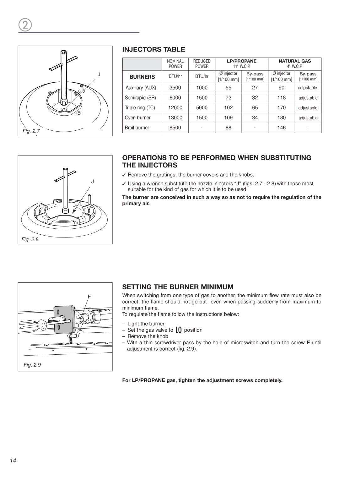
J
Fig. 2.8
OPERATIONS TO BE PERFORMED WHEN SUBSTITUTING THE INJECTORS
✓Remove the gratings, the burner covers and the knobs;
✓Using a wrench substitute the nozzle injectors “J” (figs. 2.7 - 2.8) with those most suitable for the kind of gas for which it is to be used.
The burner are conceived in such a way so as not to require the regulation of the primary air.
F |
Fig. 2.9 |
SETTING THE BURNER MINIMUM
When switching from one type of gas to another, the minimum flow rate must also be correct: the flame should not go out even when passing suddenly from maximum to minimum flame.
To regulate the flame follow the instructions below:
–Light the burner
–Set the gas valve to ![]() position
position
–Remove the knob
–With a thin screwdriver pass by the hole of microswitch and turn the screw F until adjustment is correct (fig. 2.9).
For LP/PROPANE gas, tighten the adjustment screws completely.
14