D ![]()
C
E
Fig. 25
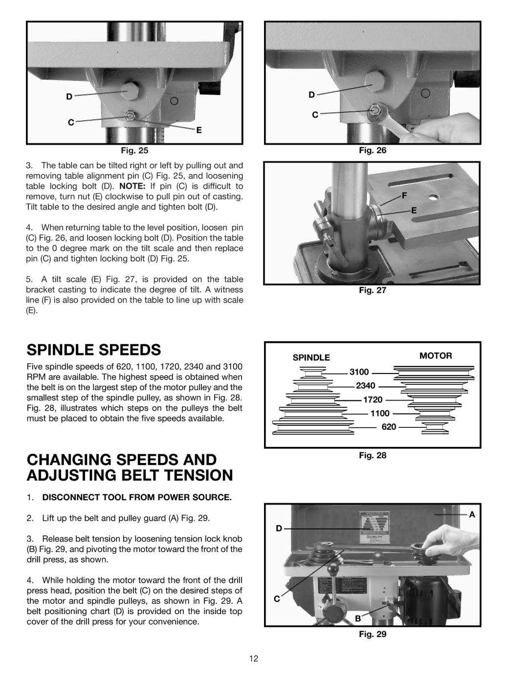
3.The table can be tilted right or left by pulling out and removing table alignment pin (C) Fig. 25, and loosening table locking bolt (D). NOTE: If pin (C) is difficult to remove, turn nut (E) clockwise to pull pin out of casting. Tilt table to the desired angle and tighten bolt (D).
4.When returning table to the level position, loosen pin
(C) Fig. 26, and loosen locking bolt (D). Position the table to the 0 degree mark on the tilt scale and then replace pin (C) and tighten locking bolt (D) Fig. 25.
5.A tilt scale (E) Fig. 27, is provided on the table bracket casting to indicate the degree of tilt. A witness line (F) is also provided on the table to line up with scale
(E).
SPINDLE SPEEDS
Five spindle speeds of 620, 1100, 1720, 2340 and 3100 RPM are available. The highest speed is obtained when the belt is on the largest step of the motor pulley and the smallest step of the spindle pulley, as shown in Fig. 28. Fig. 28, illustrates which steps on the pulleys the belt must be placed to obtain the five speeds available.
CHANGING SPEEDS AND ADJUSTING BELT TENSION
1.DISCONNECT TOOL FROM POWER SOURCE.
2.Lift up the belt and pulley guard (A) Fig. 29.
3.Release belt tension by loosening tension lock knob
(B) Fig. 29, and pivoting the motor toward the front of the drill press, as shown.
4.While holding the motor toward the front of the drill press head, position the belt (C) on the desired steps of the motor and spindle pulleys, as shown in Fig. 29. A belt positioning chart (D) is provided on the inside top cover of the drill press for your convenience.
D ![]()
C
Fig. 26
F
![]() E
E
Fig. 27
SPINDLEMOTOR
3100
2340
1720
1100
620
Fig. 28
A
D
C
B
Fig. 29
12