![]() WARNING: FOR YOUR OWN SAFETY, DO NOT CONNECT THE TOOL TO THE POWER SOURCE UNTIL THE MACHINE IS COMPLETELY ASSEMBLED AND YOU READ AND UNDERSTAND THE ENTIRE INSTRUCTION MANUAL.
WARNING: FOR YOUR OWN SAFETY, DO NOT CONNECT THE TOOL TO THE POWER SOURCE UNTIL THE MACHINE IS COMPLETELY ASSEMBLED AND YOU READ AND UNDERSTAND THE ENTIRE INSTRUCTION MANUAL.
1
2
4
7
11 |
|
| 3 |
13 |
|
8 | 6 |
| |
9 | 5 |
|
1012
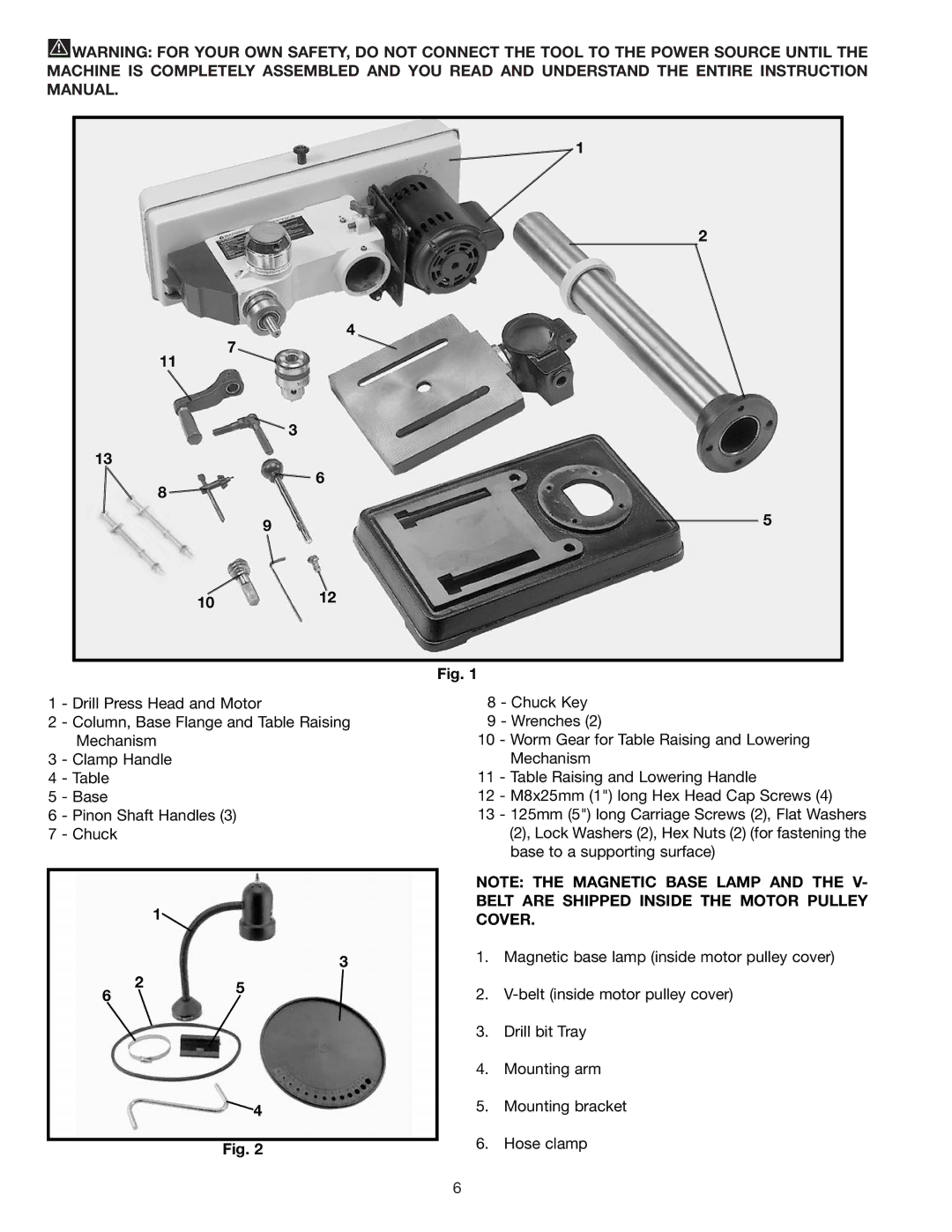
Fig. 1
1 - Drill Press Head and Motor
2 - Column, Base Flange and Table Raising
Mechanism
3 - Clamp Handle
4 - Table
5 - Base
6 - Pinon Shaft Handles (3)
7 - Chuck
1![]()
3
6 | 2 | 5 |
| ||
|
|
![]() 4
4
Fig. 2
8 - Chuck Key
9 - Wrenches (2)
10 - Worm Gear for Table Raising and Lowering Mechanism
11 - Table Raising and Lowering Handle
12 - M8x25mm (1") long Hex Head Cap Screws (4)
13 - 125mm (5") long Carriage Screws (2), Flat Washers (2), Lock Washers (2), Hex Nuts (2) (for fastening the base to a supporting surface)
NOTE: THE MAGNETIC BASE LAMP AND THE V- BELT ARE SHIPPED INSIDE THE MOTOR PULLEY COVER.
1.Magnetic base lamp (inside motor pulley cover)
2.
3.Drill bit Tray
4.Mounting arm
5.Mounting bracket
6.Hose clamp
6
