F
Fig. 7
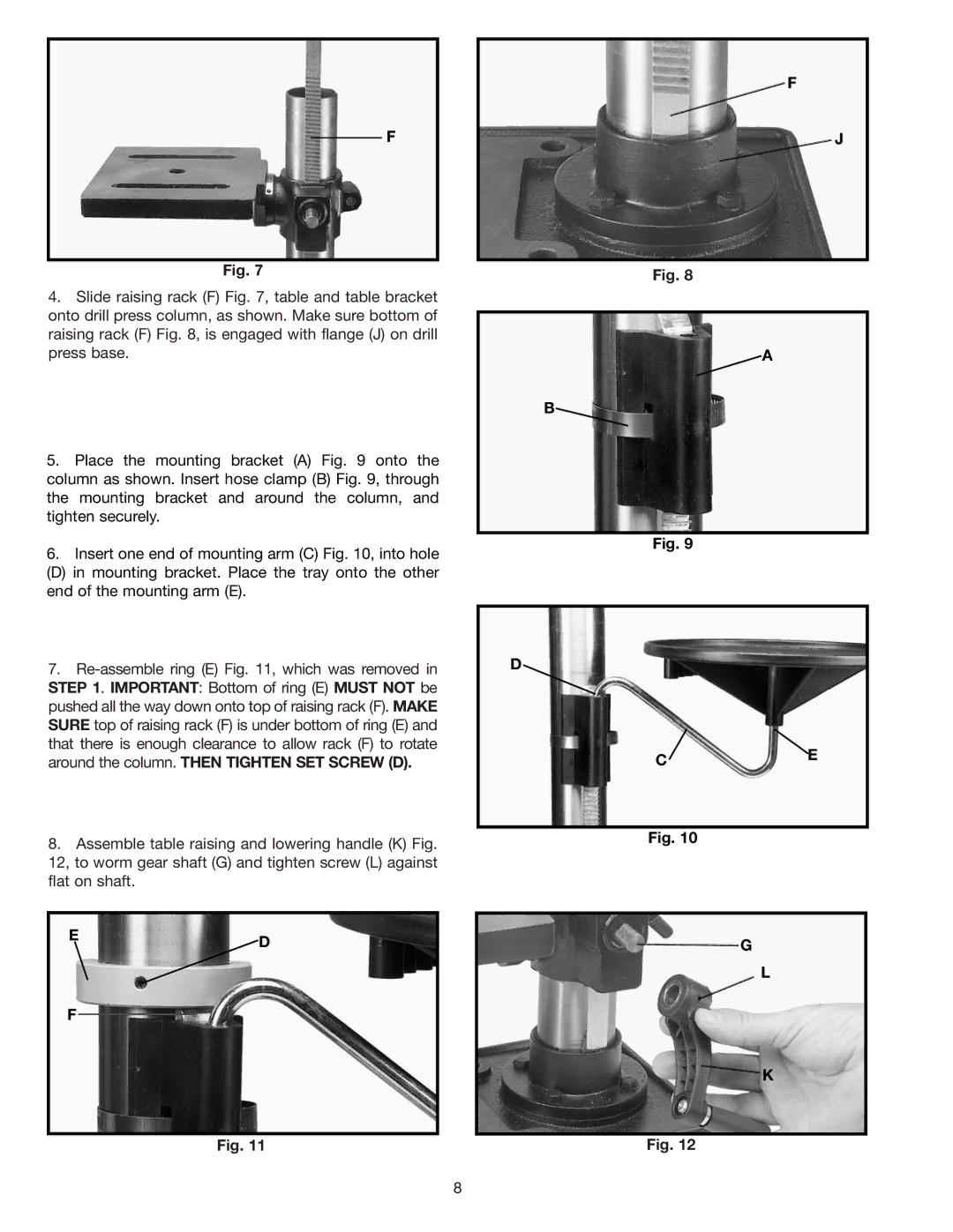
4.Slide raising rack (F) Fig. 7, table and table bracket onto drill press column, as shown. Make sure bottom of raising rack (F) Fig. 8, is engaged with flange (J) on drill press base.
5.Place the mounting bracket (A) Fig. 9 onto the column as shown. Insert hose clamp (B) Fig. 9, through the mounting bracket and around the column, and tighten securely.
6.Insert one end of mounting arm (C) Fig. 10, into hole
(D) in mounting bracket. Place the tray onto the other end of the mounting arm (E).
7.
8.Assemble table raising and lowering handle (K) Fig. 12, to worm gear shaft (G) and tighten screw (L) against flat on shaft.
ED
F
Fig. 11
![]() F
F
J
Fig. 8
![]() A
A
B![]()
Fig. 9
D
C![]() E
E
Fig. 10
G
L
![]() K
K
Fig. 12
8