CHANGING GRINDING WHEELS
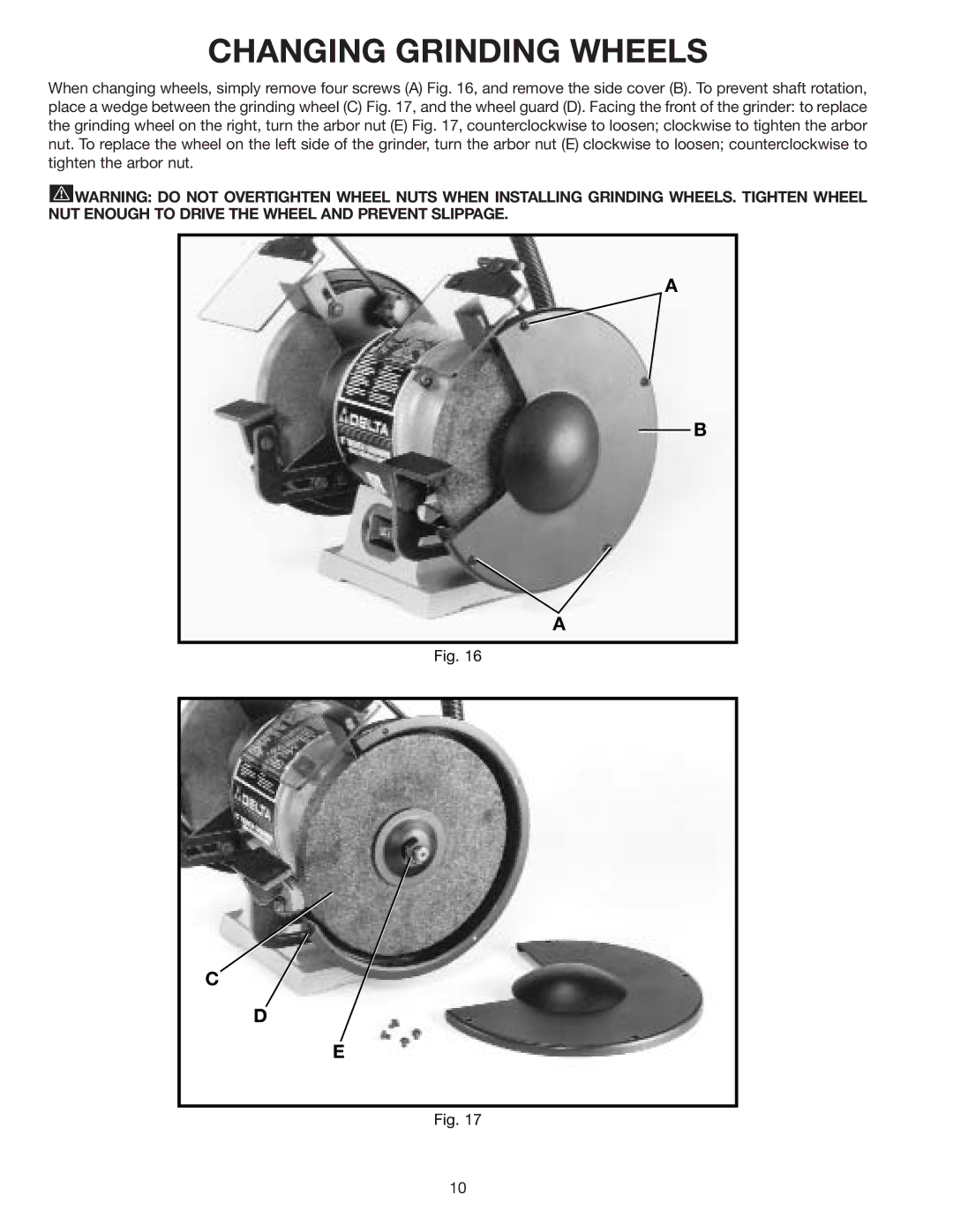
When changing wheels, simply remove four screws (A) Fig. 16, and remove the side cover (B). To prevent shaft rotation, place a wedge between the grinding wheel (C) Fig. 17, and the wheel guard (D). Facing the front of the grinder: to replace the grinding wheel on the right, turn the arbor nut (E) Fig. 17, counterclockwise to loosen; clockwise to tighten the arbor nut. To replace the wheel on the left side of the grinder, turn the arbor nut (E) clockwise to loosen; counterclockwise to tighten the arbor nut.
![]() WARNING: DO NOT OVERTIGHTEN WHEEL NUTS WHEN INSTALLING GRINDING WHEELS. TIGHTEN WHEEL NUT ENOUGH TO DRIVE THE WHEEL AND PREVENT SLIPPAGE.
WARNING: DO NOT OVERTIGHTEN WHEEL NUTS WHEN INSTALLING GRINDING WHEELS. TIGHTEN WHEEL NUT ENOUGH TO DRIVE THE WHEEL AND PREVENT SLIPPAGE.
A
B
A
Fig. 16
C
D
E
Fig. 17
10
