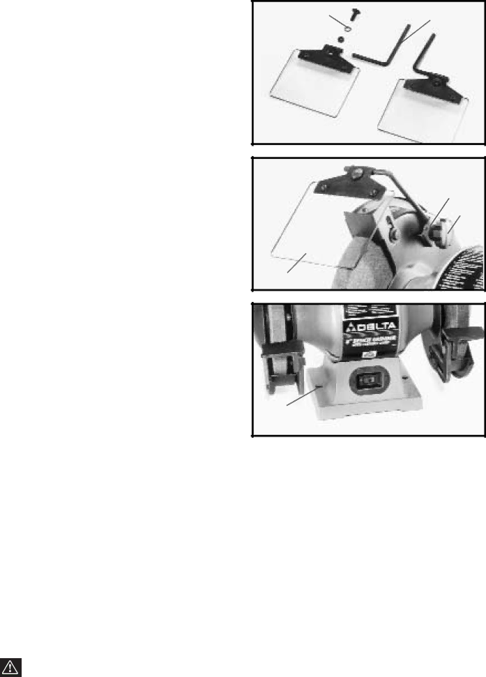
2. Insert the short end of mounting rod (F) Fig. 7, into |
hole of frame (B) and fasten in place with |
carriage head screw (G), 5/16" lock washer (H), and |
H ![]() G
G
F
3.Assemble long end of eye shield mounting rod (F) Fig. 8, to the side of each wheel guard using bracket (J), 3/8" lockwasher, and locking knob (L). The eye shield (A) is fully adjustable so it can be put in any position by moving the shield (A) or loosening locking knob (L) and repositioning rod (F). Assemble the remaining eye shield to the other wheel guard in the same manner.
B![]()
![]() I
I
Fig. 7
![]() F
F
A
Fig. 8
J
L
FASTENING GRINDER TO SUPPORTING SURFACE
IF DURING OPERATION THERE IS ANY TENDENCY FOR THE GRINDER TO TIP OVER, SLIDE OR “WALK” THE GRINDER MUST BE SECURED TO THE SUPPORT- ING SURFACE THROUGH THE HOLES (A) FIG. 9, IN THE GRINDER BASE.
A![]() A
A
Fig. 9
CONNECTING TOOL TO POWER SOURCE
POWER CONNECTIONS
A separate electrical circuit should be used for your tools. This circuit should not be less than #12 wire and should be protected with a 20 Amp time lag fuse. If an extension cord is used, use only
MOTOR SPECIFICATIONS
Your tool is wired for 120 volt, 60 HZ alternating current. Before connecting the tool to the power source, make sure the switch is in the “OFF” position. The motor provides a
GROUNDING INSTRUCTIONS
WARNING: THIS TOOL MUST BE GROUNDED WHILE IN USE TO PROTECT THE OPERATOR FROM ELECTRIC SHOCK.
7