ASSEMBLY
ASSEMBLING TOOL RESTS
1.Assemble adjustable tool rest (A) Fig. 3, to left side of tool rest arm (B), as shown, and fasten with one 5/16- 18x3/4" hex head screw and 3/8" lockwasher (C). Assemble the remaining tool rest to the right side of the other tool rest arm in the same manner. Do not com- pletely tighten hardware at this time.
2.Assemble left tool rest assembly (D) Fig. 4, to the inside of left wheel guard (E), and fasten with two
3.Assemble right tool rest assembly to the inside of right wheel guard and fasten with two
4.Each tool rest assembly (D) Fig. 4, is adjustable so it can be positioned slightly below the centerline of the wheel and as close to the grinding wheel as possible, giving maximum support to the piece that is being ground. A distance of
ASSEMBLING
SPARK GUARDS
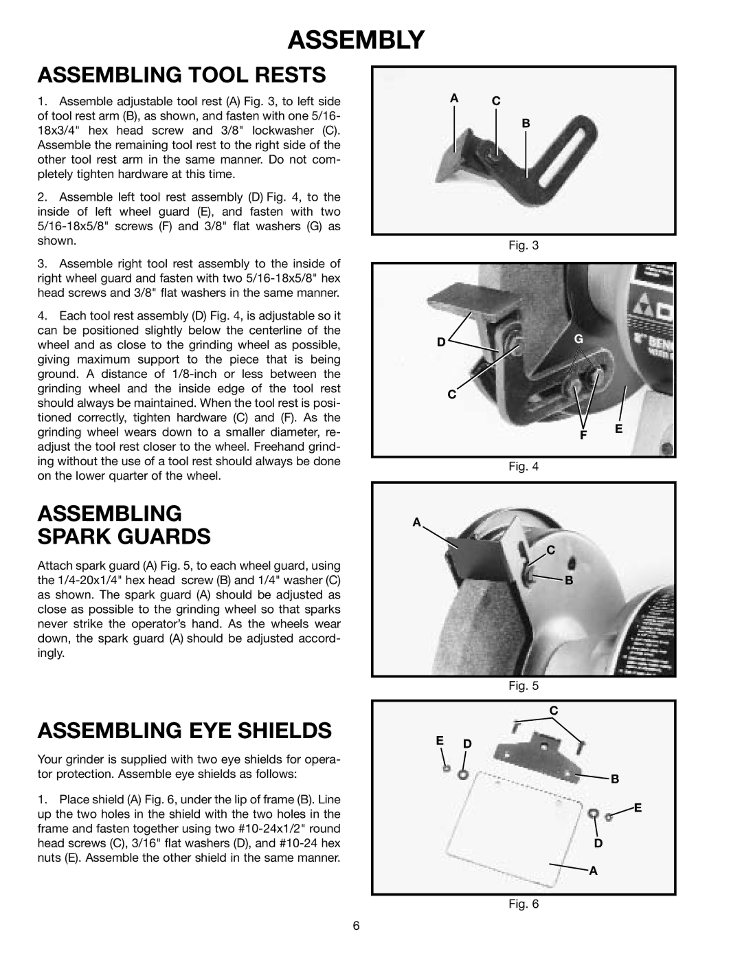
Attach spark guard (A) Fig. 5, to each wheel guard, using the
ASSEMBLING EYE SHIELDS
A C
B
Fig. 3
DG
C
F
Fig. 4
A
C
![]() B
B
Fig. 5
C
E D
E
Your grinder is supplied with two eye shields for opera- tor protection. Assemble eye shields as follows:
1.Place shield (A) Fig. 6, under the lip of frame (B). Line up the two holes in the shield with the two holes in the frame and fasten together using two
![]() B
B
![]() E
E
D
![]() A
A
Fig. 6
6