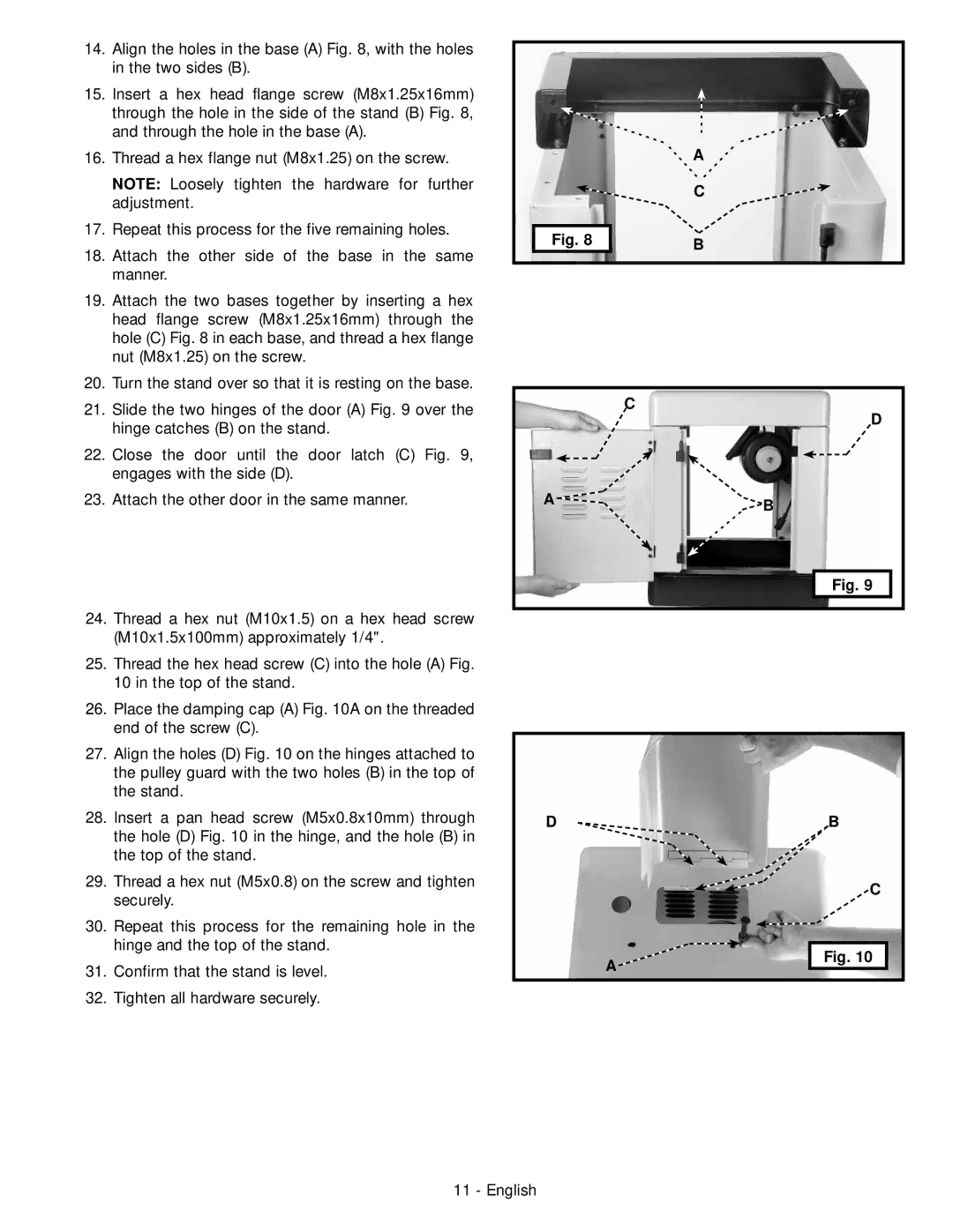
14. | Align the holes in the base (A) Fig. 8, with the holes |
| in the two sides (B). |
15. | Insert a hex head flange screw (M8x1.25x16mm) |
| through the hole in the side of the stand (B) Fig. 8, |
| and through the hole in the base (A). |
16. | Thread a hex flange nut (M8x1.25) on the screw. |
| NOTE: Loosely tighten the hardware for further |
| adjustment. |
17. | Repeat this process for the five remaining holes. |
18. | Attach the other side of the base in the same |
| manner. |
19. | Attach the two bases together by inserting a hex |
| head flange screw (M8x1.25x16mm) through the |
| hole (C) Fig. 8 in each base, and thread a hex flange |
| nut (M8x1.25) on the screw. |
20. | Turn the stand over so that it is resting on the base. |
21. | Slide the two hinges of the door (A) Fig. 9 over the |
| hinge catches (B) on the stand. |
22. | Close the door until the door latch (C) Fig. 9, |
| engages with the side (D). |
23. | Attach the other door in the same manner. |
24. Thread a hex nut (M10x1.5) on a hex head screw | |
| (M10x1.5x100mm) approximately 1/4". |
25. Thread the hex head screw (C) into the hole (A) Fig. | |
| 10 in the top of the stand. |
26. Place the damping cap (A) Fig. 10A on the threaded | |
| end of the screw (C). |
27. Align the holes (D) Fig. 10 on the hinges attached to | |
| the pulley guard with the two holes (B) in the top of |
| the stand. |
| A |
| C |
Fig. 8 | B |
|
C
D
A ![]()
![]() B
B
Fig. 9 |
28. | Insert a pan head screw (M5x0.8x10mm) through |
| the hole (D) Fig. 10 in the hinge, and the hole (B) in |
| the top of the stand. |
29. | Thread a hex nut (M5x0.8) on the screw and tighten |
| securely. |
30. | Repeat this process for the remaining hole in the |
| hinge and the top of the stand. |
31. | Confirm that the stand is level. |
32. | Tighten all hardware securely. |
D
A ![]()
B
C
Fig. 10 |
11 - English
