ADJUSTING THE TABLE STOP
This machine is equipped with an adjustable table stop
(A)Fig. 26 that allows the table to be set at 90 degrees to the blade.
Tilt the table (C) Fig. 26 to the left until the table stop
(A)Fig. 26 contacts the table. Place a square on the table against the blade (Fig. 27). If the blade is not 90 degrees to the table surface:
1. | Tilt the table slightly to the right and tighten the table |
|
| lock knobs. |
|
2. | Loosen the locknut (B) Fig. 26 to free the adjusting |
|
| screw (A) Fig. 26. Turn the adjusting screw (A) right |
|
| or left to raise or lower the table stop, then tighten |
|
| the locknut (B). |
|
3. | Lower the table. Check the angle with the square. | A |
|
|
4.When the table is 90 degrees to the blade, confirm that the pointer (E) Fig. 26 is set to 0°. If not, loosen the screw (F) Fig. 26 and move the pointer to 0°. Tighten the screw.
ADJUSTING BLADE TENSION
 Disconnect the machine from the power source!
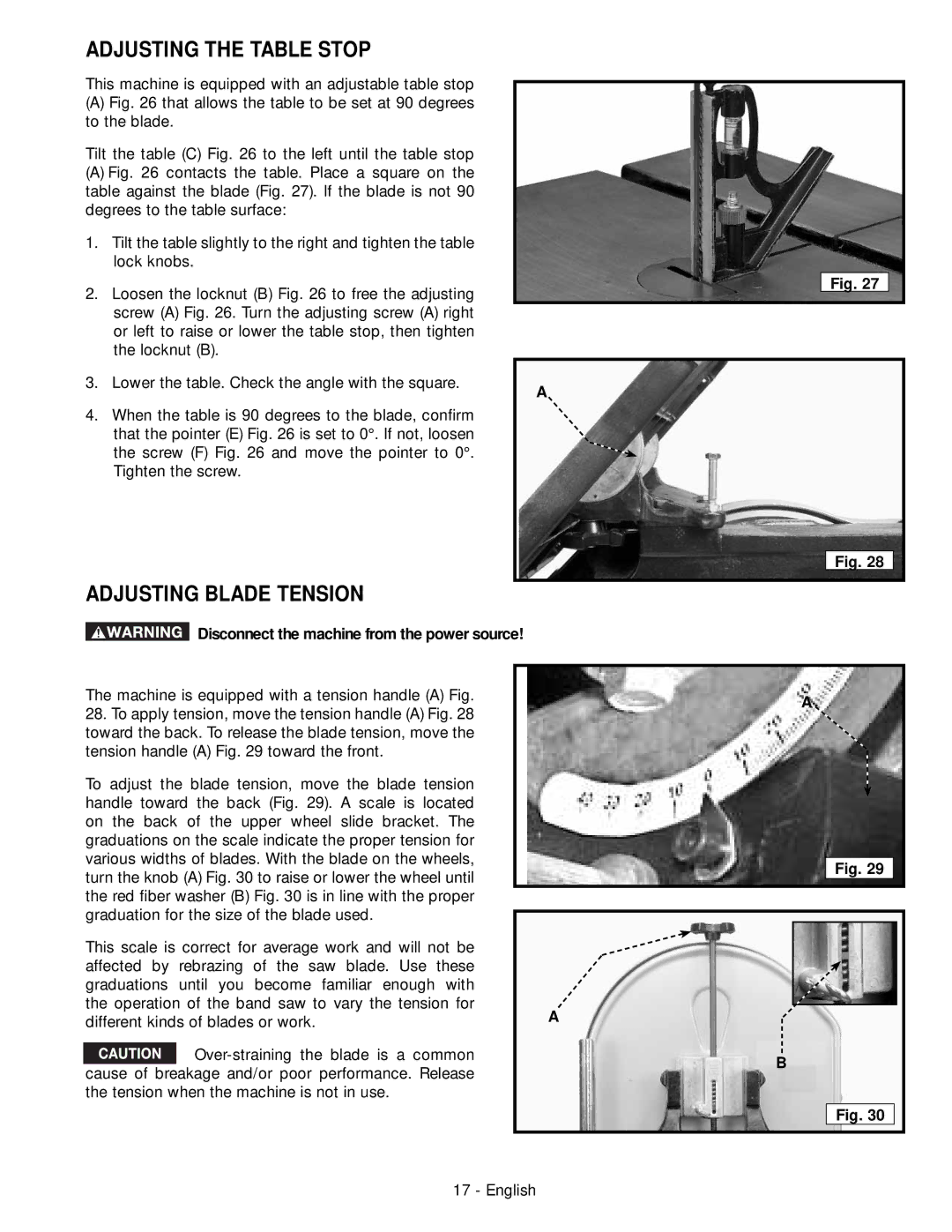
The machine is equipped with a tension handle (A) Fig.
28.To apply tension, move the tension handle (A) Fig. 28 toward the back. To release the blade tension, move the tension handle (A) Fig. 29 toward the front.
To adjust the blade tension, move the blade tension |
| |
handle toward the back (Fig. 29). A scale is located |
| |
on the back of the upper wheel slide bracket. The |
| |
graduations on the scale indicate the proper tension for |
| |
various widths of blades. With the blade on the wheels, |
| |
turn the knob (A) Fig. 30 to raise or lower the wheel until |
| |
the red fiber washer (B) Fig. 30 is in line with the proper |
| |
graduation for the size of the blade used. |
| |
This scale is correct for average work and will not be |
| |
affected by rebrazing of the saw blade. Use these |
| |
graduations until you become familiar enough with |
| |
the operation of the band saw to vary the tension for | A | |
different kinds of blades or work. | ||
| ||
| ||
cause of breakage and/or poor performance. Release |
| |
the tension when the machine is not in use. |
|
Fig. 27
Fig. 28
A
Fig. 29
B
Fig. 30
17 - English