ADJUSTING UPPER BLADE
GUIDE ASSEMBLY
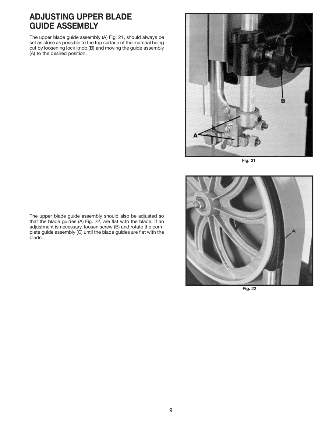
The upper blade guide assembly (A) Fig. 21, should always be set as close as possible to the top surface of the material being cut by loosening lock knob (B) and moving the guide assembly
(A) to the desired position.
Fig. 21
The upper blade guide assembly should also be adjusted so that the blade guides (A) Fig. 22, are flat with the blade. If an adjustment is necessary, loosen screw (B) and rotate the com- plete guide assembly (C) until the blade guides are flat with the blade.
Fig. 22
9
