ADJUSTMENTS
ADJUSTING MITER GAGE SLOT ALIGNMENT
M a k e c e r t a i n m a c h i n e i s disconnected from power source
before making adjustments.
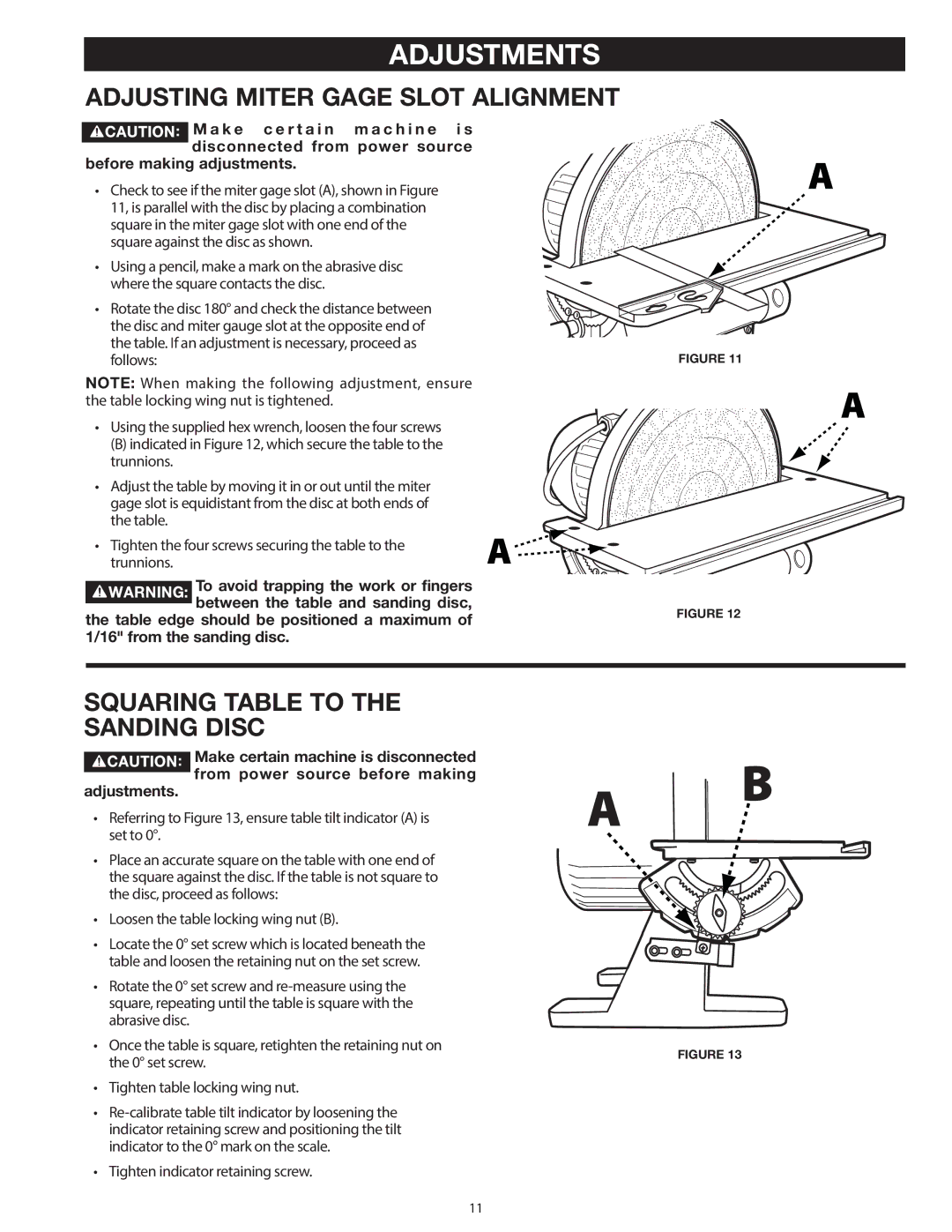
• Check to see if the miter gage slot (A), shown in Figure 11, is parallel with the disc by placing a combination square in the miter gage slot with one end of the square against the disc as shown.
• Using a pencil, make a mark on the abrasive disc where the square contacts the disc.
• Rotate the disc 180° and check the distance between the disc and miter gauge slot at the opposite end of the table. If an adjustment is necessary, proceed as follows:
NOTE: When making the following adjustment, ensure the table locking wing nut is tightened.
• Using the supplied hex wrench, loosen the four screws
(B) indicated in Figure 12, which secure the table to the trunnions.
• Adjust the table by moving it in or out until the miter gage slot is equidistant from the disc at both ends of the table.
• Tighten the four screws securing the table to the trunnions.
To avoid trapping the work or fingers ![]() between the table and sanding disc, the table edge should be positioned a maximum of
between the table and sanding disc, the table edge should be positioned a maximum of
1/16" from the sanding disc.
FIGURE 11
FIGURE 12
SQUARING TABLE TO THE SANDING DISC
Make certain machine is disconnected from power source before making
adjustments.
•Referring to Figure 13, ensure table tilt indicator (A) is set to 0°.
•Place an accurate square on the table with one end of the square against the disc. If the table is not square to the disc, proceed as follows:
•Loosen the table locking wing nut (B).
•Locate the 0° set screw which is located beneath the table and loosen the retaining nut on the set screw.
•Rotate the 0° set screw and
•Once the table is square, retighten the retaining nut on the 0° set screw.
•Tighten table locking wing nut.
•
•Tighten indicator retaining screw.
FIGURE 13
11
