MOVING CUTTINGHEAD TO THE UP POSITION
B
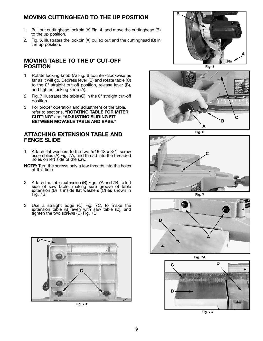
1.Pull out cuttinghead lockpin (A) Fig. 4, and move the cuttinghead (B) to the up position.
2.Fig. 5, illustrates the lockpin (A) pulled out and the cuttinghead (B) in the up position.
A
MOVING TABLE TO THE 0° |
|
POSITION | Fig. 5 |
1.Rotate locking knob (A) Fig. 6
2.Fig. 7 illustrates the table (C) in the 0° straight cut-off position.
3.For proper operation and adjustment of the table, refer to sections, “ROTATING TABLE FOR MITER
CUTTING” and “ADJUSTING SLIDING FIT | C |
BETWEEN MOVABLE TABLE AND BASE.” | B |
| A |
ATTACHING EXTENSION TABLE AND FENCE SLIDE
1.Attach flat washers to the two
NOTE: Turn the screws only a few threads into the holes at this time.
2.Attach the table extension (B) Figs. 7A and 7B, to left side of saw table, making sure groove of table extension (B) is inside flat washers (C) as shown in Fig. 7B.
3.Use a straight edge (C) Fig. 7C, to make the extension table (B) even with saw table (D), and tighten the two screws (C) Fig. 7B.
B ![]()
C
Fig. 6
C
Fig. 7
B
A
Fig. 7A
CD
B
Fig. 7B
Fig. 7C
9