ASSEMBLY INSTRUCTIONS
WARNING: FOR YOUR OWN SAFETY, DO NOT CONNECT THE SHAPER TO THE POWER SOURCE UNTIL THE SHAPER IS COMPLETELY ASSEMBLED AND YOU HAVE READ AND UNDERSTOOD THE ENTIRE INSTRUCTION MANUAL.
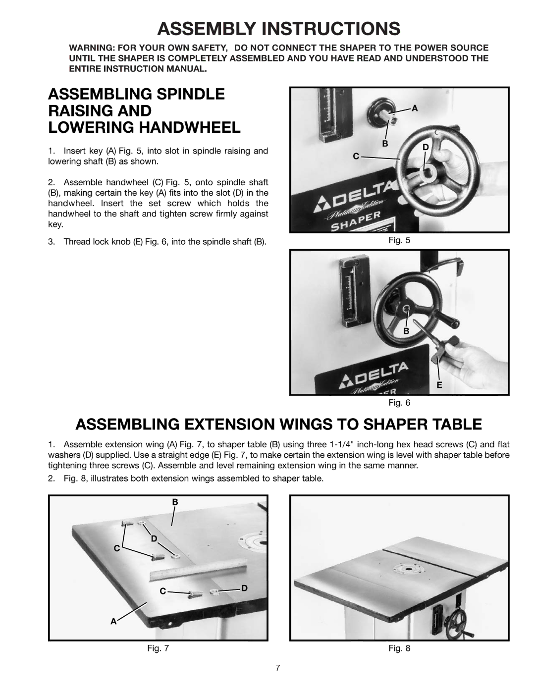
ASSEMBLING SPINDLE RAISING AND LOWERING HANDWHEEL
1.Insert key (A) Fig. 5, into slot in spindle raising and lowering shaft (B) as shown.
2.Assemble handwheel (C) Fig. 5, onto spindle shaft (B), making certain the key (A) fits into the slot (D) in the handwheel. Insert the set screw which holds the handwheel to the shaft and tighten screw firmly against key.
3.Thread lock knob (E) Fig. 6, into the spindle shaft (B).
A
B D
C
Fig. 5
B
E
Fig. 6
ASSEMBLING EXTENSION WINGS TO SHAPER TABLE
1.Assemble extension wing (A) Fig. 7, to shaper table (B) using three
2.Fig. 8, illustrates both extension wings assembled to shaper table.
B
D
C
C ![]()
![]() D
D
A
Fig. 7 | Fig. 8 |
7