ASSEMBLY
![]() WARNING: FOR YOUR OWN SAFETY, DO NOT CONNECT THE MACHINE TO THE POWER SOURCE UNTIL THE MACHINE IS COMPLETELY ASSEMBLED AND YOU READ AND UNDERSTAND THE ENTIRE INSTRUCTION MANUAL.
WARNING: FOR YOUR OWN SAFETY, DO NOT CONNECT THE MACHINE TO THE POWER SOURCE UNTIL THE MACHINE IS COMPLETELY ASSEMBLED AND YOU READ AND UNDERSTAND THE ENTIRE INSTRUCTION MANUAL.
ASSEMBLING CASTER ASSEMBLIES TO BASE
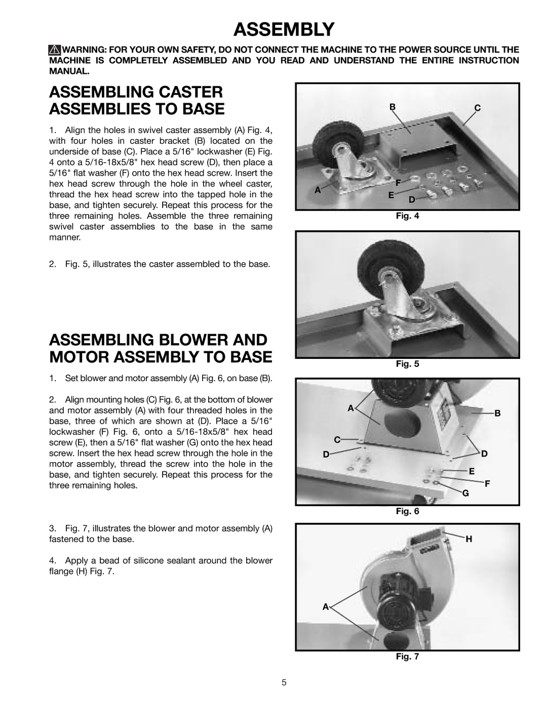
1.Align the holes in swivel caster assembly (A) Fig. 4, with four holes in caster bracket (B) located on the underside of base (C). Place a 5/16" lockwasher (E) Fig.
4onto a
2.Fig. 5, illustrates the caster assembled to the base.
ASSEMBLING BLOWER AND MOTOR ASSEMBLY TO BASE
BC
A |
| F | |
E | D | ||
| |||
|
| ||
|
| Fig. 4 |
Fig. 5
1. Set blower and motor assembly (A) Fig. 6, on base (B). |
2. Align mounting holes (C) Fig. 6, at the bottom of blower |
and motor assembly (A) with four threaded holes in the |
base, three of which are shown at (D). Place a 5/16" |
lockwasher (F) Fig. 6, onto a |
screw (E), then a 5/16" flat washer (G) onto the hex head |
A
C
B
screw. Insert the hex head screw through the hole in the | |
motor assembly, thread the screw into the hole in the | |
base, and tighten securely. Repeat this process for the | |
three remaining holes. | |
3. | Fig. 7, illustrates the blower and motor assembly (A) |
fastened to the base. | |
4. | Apply a bead of silicone sealant around the blower |
flange (H) Fig. 7. | |
D![]()
![]() D
D
![]() E
E
F
G
Fig. 6
H
A
Fig. 7
5