3.Position open end of filter bag (A) Fig. 20, over upper lip of support drum (E). Insert locking band (F) Fig. 20, through the loops of filter bag (A) and fasten with clamp (G) as shown in Fig. 21. NOTE: Make certain locking band (F) Fig. 20, is positioned in the channel of drum (E) before fastening clamp (G) Fig. 21.
4.Pull up on each retaining clip (A) Fig. 22, and insert the dust collection bag (B) underneath each retaining clip to hold the dust collection bag in place.
5.Place the locking clamp (C) Fig. 22 around dust collection bag and dust collector drum and lock in place.
NOTE: Make certain locking clamp is positioned in the channel of the dust collector drum before locking clamp.
A
FF
G
E
Fig. 20
G
Fig. 21
ASSEMBLING DUST INTAKE PORT TO BLOWER AND MOTOR ASSEMBLY
1.MAKE CERTAIN THE DUST COLLECTOR IS DISCONNECTED FROM THE POWER SOURCE.
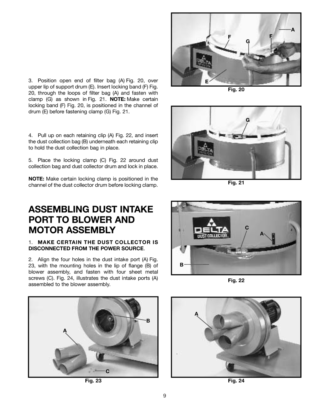
2.Align the four holes in the dust intake port (A) Fig. 23, with the mounting holes in the lip of flange (B) of blower assembly, and fasten with four sheet metal screws (C). Fig. 24, illustrates the dust intake ports (A) assembled to the blower assembly.
B
A
C
Fig. 23
C
A![]()
B
Fig. 22
A
Fig. 24
9