Manuals
/
Delta
/
Computer Equipment
/
Cash Register
Delta
TE-4000
manual
Hardware Specification
Models:
TE-4000
1
7
55
55
Download
55 pages
35.09 Kb
4
5
6
7
8
9
10
11
Specs
Error codes
Wiring diagram
Hardware Configuration
Quick SET UP
Page 7
Image 7
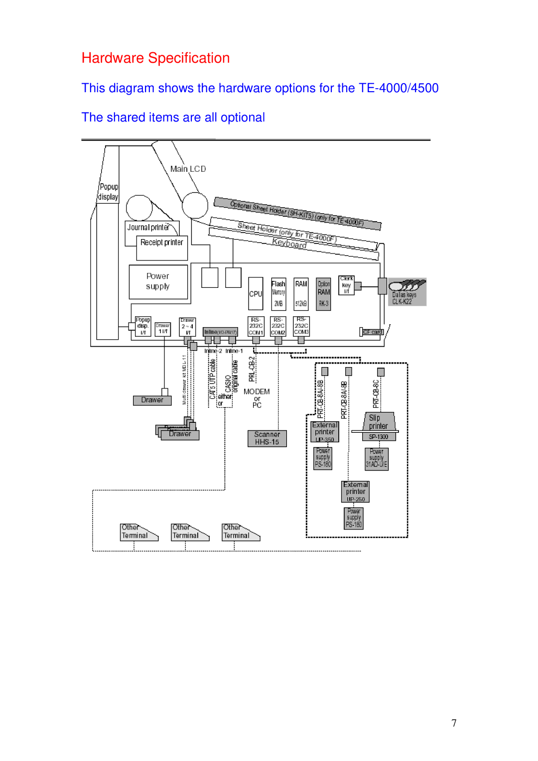
Hardware Specification
This diagram shows the hardware options for the
TE-4000/4500
The shared items are all optional
7
Page 6
Page 8
Page 7
Image 7
Page 6
Page 8
Contents
November
TK- 4000 Quick SET UP Guide Chapters
Chapter
Hardware Configuration
Cable Specifications
Page
Page
Hardware Specification
Loading the IPL
Quick SET UP
On the cash register
Loading the IPL via the CF card to the terminal
Loading the IPL via PC
Wiring diagram
On the cash register
Initialising Terminal
How to Initialises the cash register in detail
To reprogram the terminal ID after initialisation
Memory Allocation
Quick set up
New files in the memory allocation
Memory allocation
Memory Allocation sheets
Program / Buffer files
Free Function Keys
Assigning Function Keys
New Function Key
Keyboard Worksheet
Function keys for Pubs and Restaurants
Operator Number Key
New Balance
New / Old Check
#/NS
Tray Total
Text Recall
Quick SET UP Guide
Setting UP the IN-LINE Network
Master
Setting up the In-Line network in detail
MasterSatellite
Page
Sending the In-line connection table across the network
Master Satellite
Explanation of different types of check tracking systems
Self Master System
Setting UP Shared Check Tracking
Setting up Shared check tracking in detail
Page
If you are using clerk interrupt and check tracking
To Program to a range of clerks
To add to a check/table more than once
Use the procedure below to program the table transfer key
Setting UP Floating Clerk Interrupt
How to set up floating clerk Interrupt in detail
Page
Setting UP Shared Printing
How to set up shared printing in detail
External printer
Operation
Setting UP Time Attendence
Time and attendance in detail
Page
Setting UP Graphic LOGO’S
Page
Page
Page
CF Card Options
In-Line send and receive
Dallas Keys
2622
To allow use of magnetic Dallas keys Turn to program mode
Error Codes
Top
Page
Image
Contents