2 INTRODUCTION
2-1 Theory of operation
The main topology of the UPS consists of bypass path,
Description of block diagram
B r e a k e r
A C I/P
E M I Filter
|
| B Y P A S S |
|
|
|
P F C C o n t r o l | L E D B o a r d | C o n t r o l B o a r d |
|
| |
Circuit |
|
| |||
|
|
|
|
| |
T o C o n t r o l B o a r d |
|
|
| ||
|
| To Auxiliary Power |
|
|
|
R e l a y |
|
|
|
| B Y P A S S |
|
|
|
|
| R E L A Y |
A C - D C D o u b l e |
|
| Half - bridge DC - AC Inverter | A C | O / P |
Booster |
|
| |||
|
|
|
|
| |
Battery Bank |
|
|
|
|
|
C h a r g e r |
| D C - D C C o n v e r t e r |
|
|
|
|
| T o C o n t r o l B o a r d |
|
|
|
T o C o n t r o l B o a r d |
|
|
|
|
|
|
| Auxiliary |
|
|
|
To External Battery Bank | P o w e r |
|
|
| |
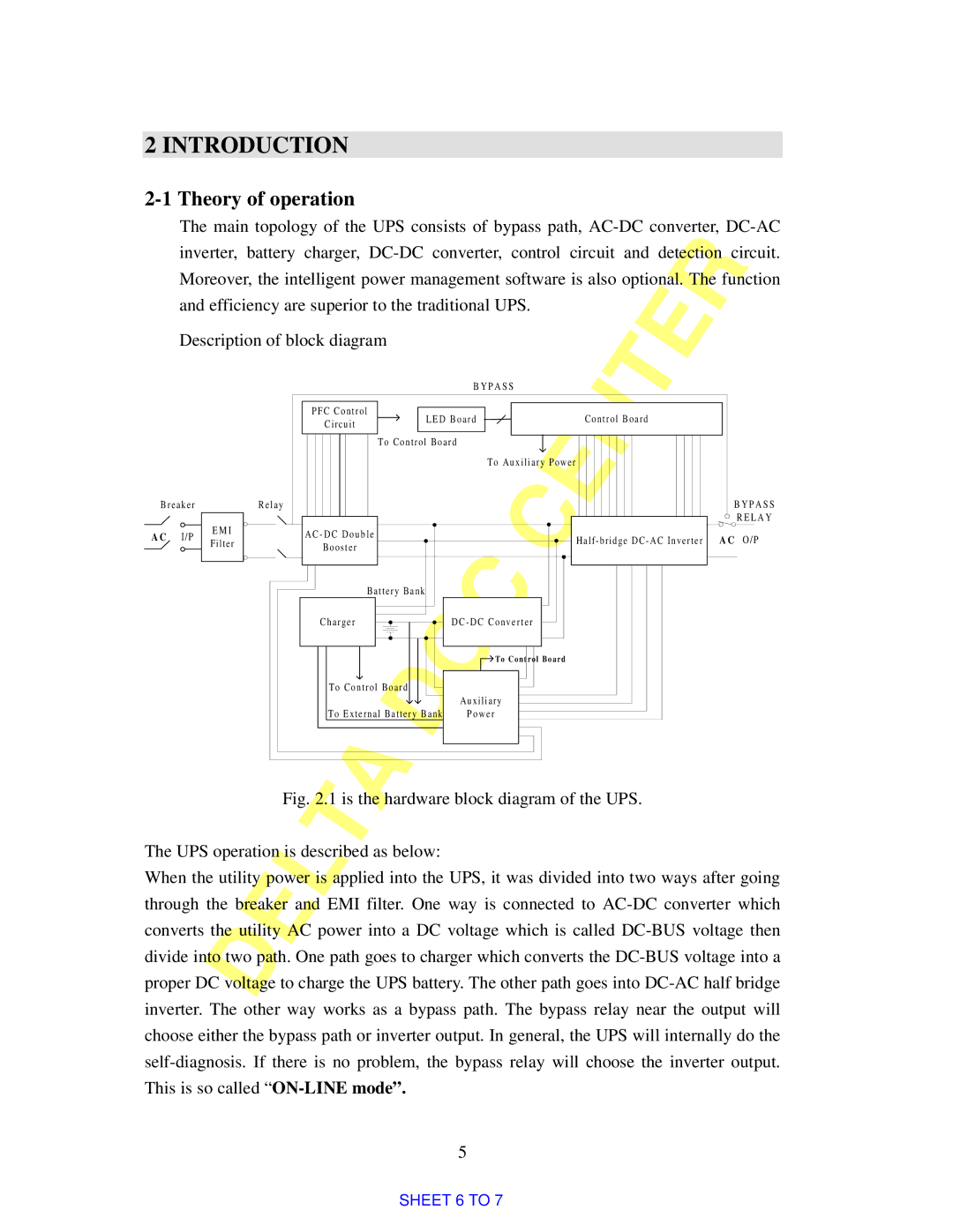
Fig. 2.1 is the hardware block diagram of the UPS.
The UPS operation is described as below:
When the utility power is applied into the UPS, it was divided into two ways after going through the breaker and EMI filter. One way is connected to AC-DC converter which converts the utility AC power into a DC voltage which is called DC-BUS voltage then divide into two path. One path goes to charger which converts the DC-BUS voltage into a proper DC voltage to charge the UPS battery. The other path goes into DC-AC half bridge inverter. The other way works as a bypass path. The bypass relay near the output will choose either the bypass path or inverter output. In general, the UPS will internally do the self-diagnosis. If there is no problem, the bypass relay will choose the inverter output. This is so called “ON-LINE mode”.
5
SHEET 6 TO 7
