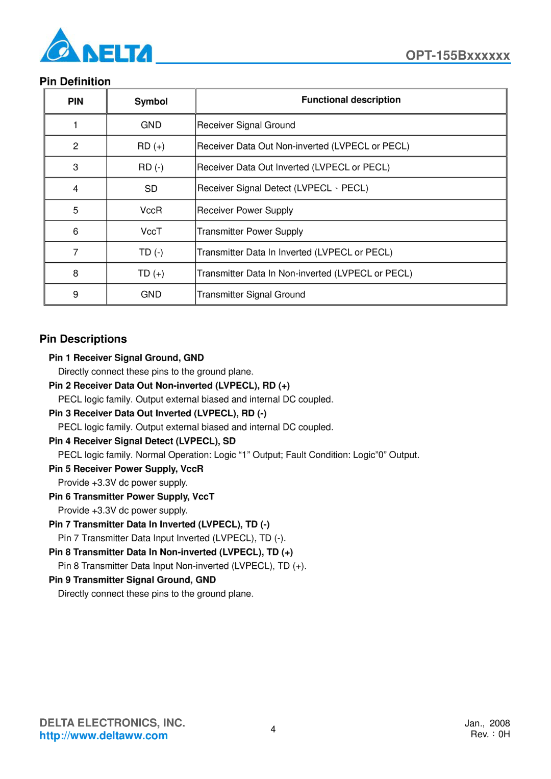
OPT-155Bxxxxxx specifications
Delta Electronics is renowned for its cutting-edge advancements in power solutions, and the OPT-155Bxxxxxx series exemplifies this dedication to innovation. Among its many offerings, the OPT-155Bxxxxxx stands out for its reliability, efficiency, and versatility, making it an ideal choice for various applications ranging from industrial automation to renewable energy systems.One of the key features of the OPT-155Bxxxxxx is its high efficiency rating, often exceeding 90%. This translates to lower energy consumption and reduced operational costs, which is essential in environments that require continuous and reliable power supply. The power supply is designed to minimize heat generation, allowing for lower cooling costs and prolonged component lifespan. Additionally, this series incorporates advanced thermal management technologies to ensure optimal performance even under demanding conditions.
In terms of design, the OPT-155Bxxxxxx is compact, allowing for easy integration into existing systems without significant spatial constraints. The robust construction quality ensures durability even in challenging environments, including those with high humidity or dust levels. This makes it particularly suitable for use in industrial settings where equipment often faces harsh conditions.
The OPT-155Bxxxxxx is equipped with several protective features, including over-voltage protection, over-current protection, and short-circuit protection, ensuring safe operation and minimizing damage risk. It is compliant with international standards such as UL, CE, and RoHS, highlighting its suitability for global markets.
Connectivity and flexibility are also hallmarks of the OPT-155Bxxxxxx series. It supports various input voltage ranges, accommodating different geographical and operational requirements. Furthermore, it is compatible with a range of communication protocols, enabling seamless integration into advanced control systems and IoT environments.
In summary, Delta Electronics' OPT-155Bxxxxxx series represents a significant advancement in power supply technology. With its focus on efficiency, durability, and versatility, it serves as an essential component for industries seeking reliable power solutions. Whether utilized in manufacturing, renewable energy, or automation, the OPT-155Bxxxxxx series continues to set the benchmark for quality and performance in the power supply market. This makes it a noteworthy option for engineers and decision-makers looking to enhance their operational capabilities while prioritizing efficiency and safety.

