ELECTRICAL CHARACTERISTICS CURVES
Copper Strip |
|
|
|
Vo(+) |
|
|
|
10u | 1u | SCOPE | RESISTIVE |
| LOAD | ||
|
|
| |
|
|
|
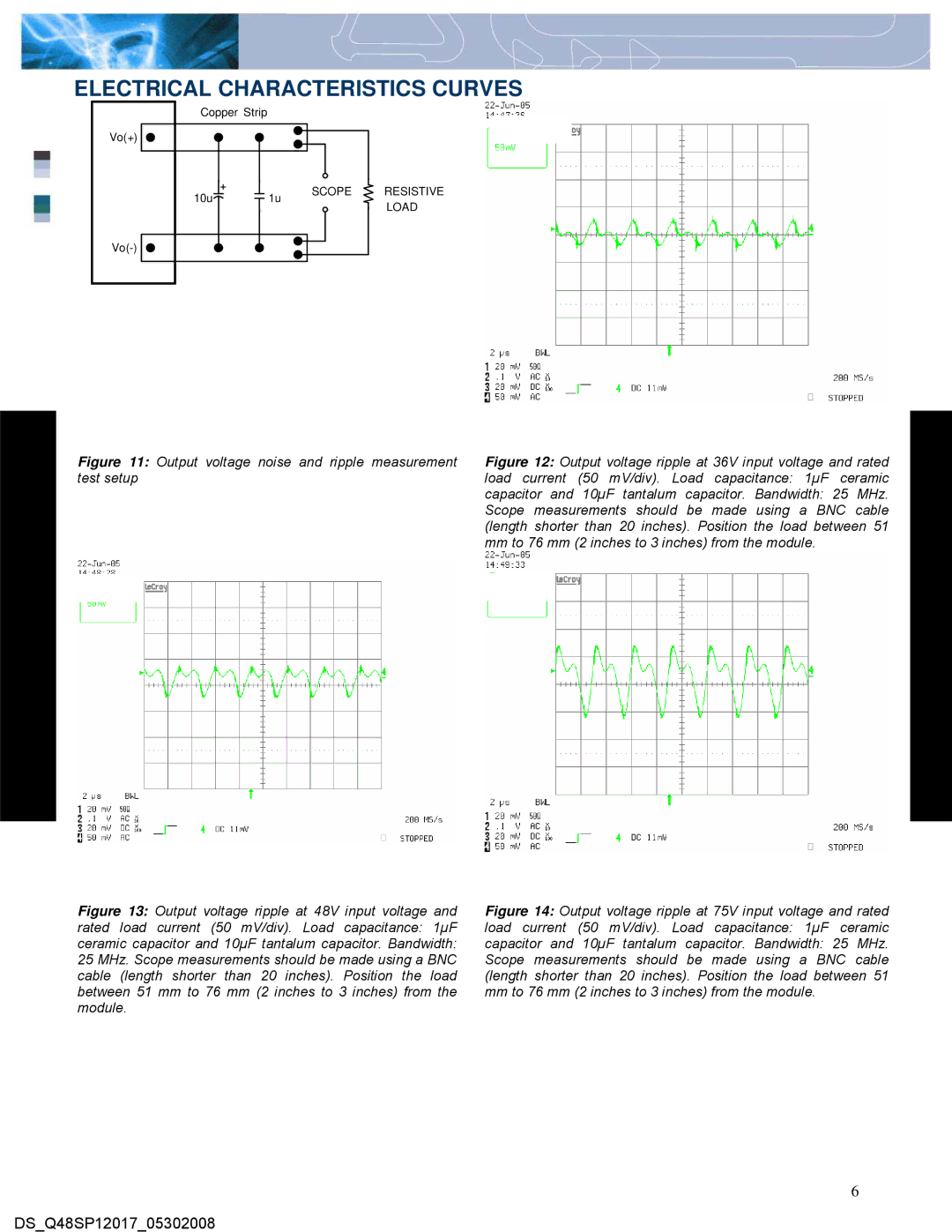
Figure 11: Output voltage noise and ripple measurement test setup
Figure 12: Output voltage ripple at 36V input voltage and rated
load current (50 mV/div). Load capacitance: 1µF ceramic
capacitor and 10µF tantalum capacitor. Bandwidth: 25 MHz. Scope measurements should be made using a BNC cable (length shorter than 20 inches). Position the load between 51 mm to 76 mm (2 inches to 3 inches) from the module.
Figure 13: Output voltage ripple at 48V input voltage and
rated load current (50 mV/div). Load capacitance: 1µF ceramic capacitor and 10µF tantalum capacitor. Bandwidth: 25 MHz. Scope measurements should be made using a BNC cable (length shorter than 20 inches). Position the load between 51 mm to 76 mm (2 inches to 3 inches) from the module.
Figure 14: Output voltage ripple at 75V input voltage and rated
load current (50 mV/div). Load capacitance: 1µF ceramic
capacitor and 10µF tantalum capacitor. Bandwidth: 25 MHz. Scope measurements should be made using a BNC cable (length shorter than 20 inches). Position the load between 51 mm to 76 mm (2 inches to 3 inches) from the module.
6
DS_Q48SP12017_05302008