FEATURES DESCRIPTIONS (CON.)
Output Voltage Adjustment (TRIM) (Not applicable to Q48SP120017Exxx)
To increase or decrease the output voltage set point, connect an external resistor between the TRIM pin and either the SENSE(+) or
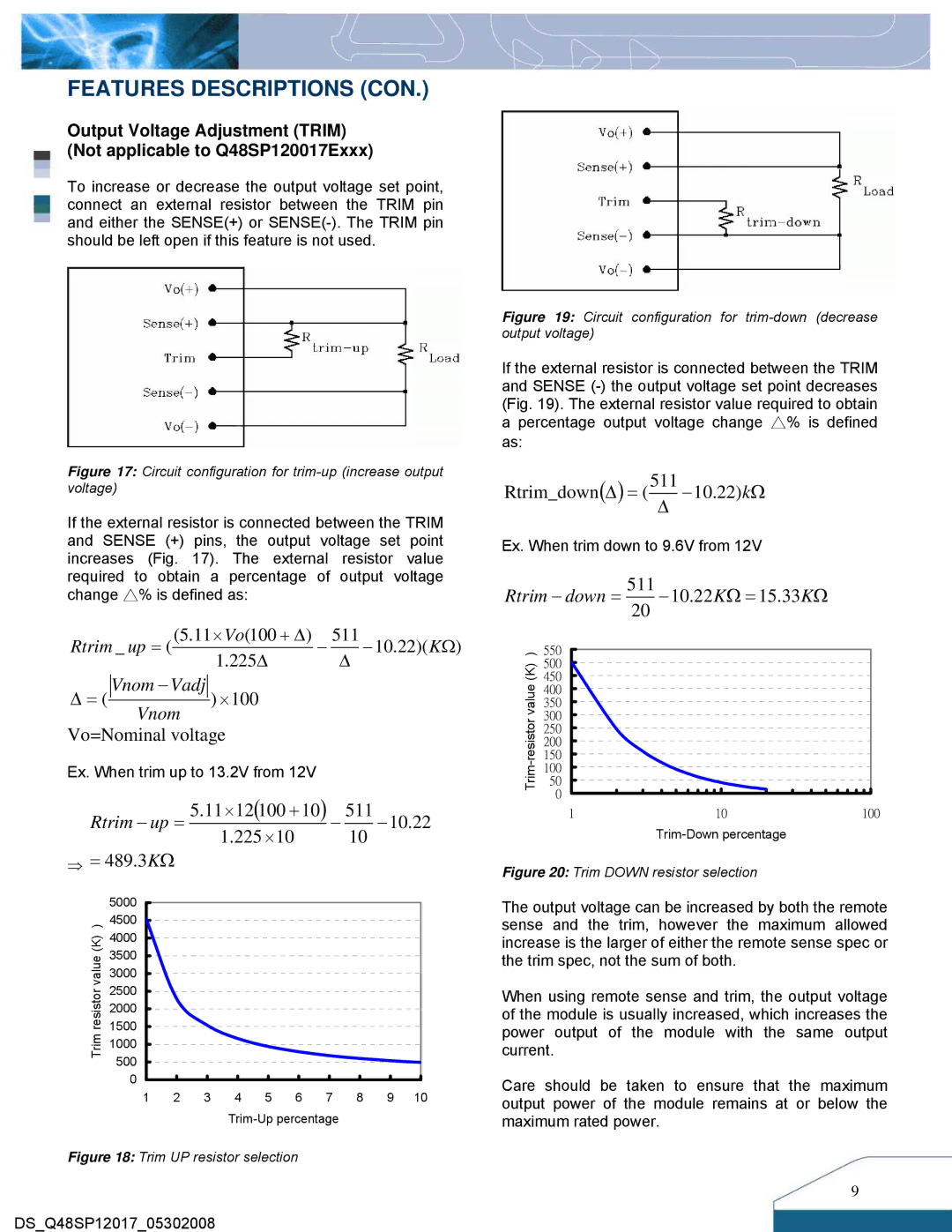
Figure 17: Circuit configuration for trim-up (increase output voltage)
If the external resistor is connected between the TRIM and SENSE (+) pins, the output voltage set point increases (Fig. 17). The external resistor value required to obtain a percentage of output voltage change △% is defined as:
Rtrim _ up = ((5.11×Vo(100 + Δ) − 511 −10.22)(KΩ)
1.225Δ Δ
Δ= ( Vnom −Vadj ) ×100 Vnom
Vo=Nominal voltage
Ex. When trim up to 13.2V from 12V
Rtrim − up = 5.11×12(100 +10) − 511 −10.22
1.225 ×10 10
⇒= 489.3KΩ
| 5000 | |
) | 4500 | |
(K) | 4000 | |
3500 | ||
value | ||
3000 | ||
| ||
resistor | 2500 | |
2000 | ||
| ||
Trim | 1500 | |
1000 | ||
| ||
| 500 | |
| 0 |
1 | 2 | 3 | 4 | 5 | 6 | 7 | 8 | 9 | 10 |
Figure 18: Trim UP resistor selection
DS_Q48SP12017_05302008
Figure 19: Circuit configuration for trim-down (decrease output voltage)
If the external resistor is connected between the TRIM and SENSE
Rtrim_down(Δ) = (511Δ −10.22)kΩ
Ex. When trim down to 9.6V from 12V
Rtrim − down = | 511 | −10.22KΩ = 15.33KΩ |
| |
|
| 20 |
|
|
) | 550 |
|
|
|
(K) | 500 |
|
|
|
450 |
|
|
| |
value | 400 |
|
|
|
350 |
|
|
| |
|
|
|
| |
300 |
|
|
| |
250 |
|
|
| |
|
|
|
| |
| 200 |
|
|
|
| 150 |
|
|
|
| 100 |
|
|
|
| 50 |
|
|
|
| 0 |
|
|
|
| 1 |
| 10 | 100 |
|
|
|
| |
Figure 20: Trim DOWN resistor selection
The output voltage can be increased by both the remote sense and the trim, however the maximum allowed increase is the larger of either the remote sense spec or the trim spec, not the sum of both.
When using remote sense and trim, the output voltage of the module is usually increased, which increases the power output of the module with the same output current.
Care should be taken to ensure that the maximum output power of the module remains at or below the maximum rated power.
9