Sprayer specifications
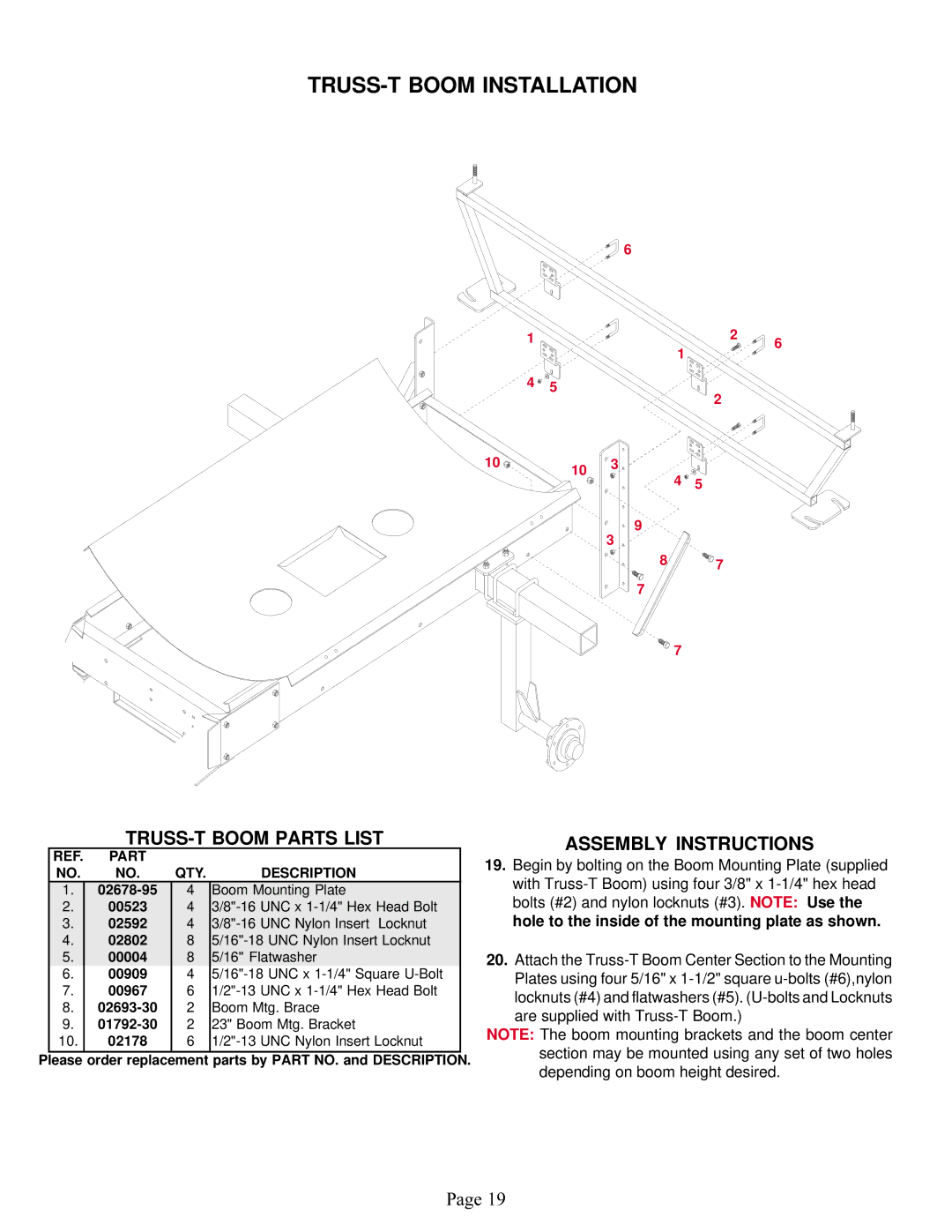
The Demco Sprayer is a leading solution for farmers looking for efficient and effective crop management. Renowned for its durability and versatile applications, the sprayer stands out with several key features and advanced technologies designed to enhance productivity.One of the most notable characteristics of Demco Sprayer is its robust construction. Built with high-quality materials, the sprayer is engineered to withstand harsh agricultural conditions, ensuring longevity and reliability. The frame is designed to optimize weight distribution, which not only enhances stability during operation but also reduces soil compaction.
The Demco Sprayer is equipped with a state-of-the-art spray system that provides even and consistent coverage. This is vital for optimizing pesticide and fertilizer application. The sprayer features adjustable nozzles that can be tailored to specific crop requirements and environmental conditions. This adaptability reduces the risk of crop damage and ensures that chemicals are applied effectively, maximizing the yield.
Another significant advancement in Demco Sprayers is their user-friendly control system. Operators appreciate the intuitive design that simplifies adjustments to pressure and flow rates while in the field. This allows for real-time modifications that can improve efficiency and effectiveness without having to stop operations. Additionally, many models come with automatic shut-off features, helping to conserve resources and reduce waste.
The integration of modern GPS technology further elevates the performance of Demco Sprayers. This technology enables precise application by allowing farmers to map out fields and ensure that every area receives the necessary treatment. It significantly reduces overlaps and missed spots, which can lead to waste and under-application of critical nutrients.
Capacity is another hallmark of the Demco Sprayer lineup. With various tank sizes available, farmers can select the sprayer that best fits their operational needs, whether for small-scale applications or large farm acreage. Flexibility in tank sizes ensures that the sprayer can cater to different farming operations without compromising efficiency.
Finally, ease of maintenance is an essential aspect of the design. Demco Sprayers often feature accessible components that allow for quick inspections and repairs, minimizing downtime during critical farming seasons. Coupled with robust customer support and warranty options, owners can feel confident in their investment.
In summary, the Demco Sprayer combines advanced technologies, robust construction, user-friendly controls, and flexibility to provide an exceptional solution for modern agriculture. Its focus on efficiency, ease of use, and durability makes it an indispensable tool for farmers looking to enhance their productivity.

